How to Use H-bridge motor driver: Examples, Pinouts, and Specs
Introduction
An H-bridge motor driver is an electronic circuit designed to control the direction and speed of DC motors. By enabling a voltage to be applied across a motor in either direction, it allows for forward and reverse motion. The "H" in its name comes from the arrangement of four switches (transistors or MOSFETs) in an "H" configuration. This versatile component is widely used in robotics, automation systems, and motorized devices.
Explore Projects Built with H-bridge motor driver

Explore Projects Built with H-bridge motor driver
Common Applications and Use Cases
- Robotics: Controlling the movement of robot wheels or arms.
- Automation: Driving conveyor belts or actuators.
- Remote-controlled vehicles: Enabling forward and reverse motion.
- Motorized toys: Providing directional control for DC motors.
- Industrial machinery: Operating motors in automated systems.
Technical Specifications
Below are the general technical specifications for a typical H-bridge motor driver. Specific values may vary depending on the model (e.g., L298N, L293D, or DRV8833).
Key Technical Details
- Operating Voltage: 5V to 35V (varies by model)
- Output Current: 1A to 2A per channel (continuous), up to 3A peak
- Logic Voltage: 3.3V or 5V (for control signals)
- Number of Channels: 1 or 2 (single or dual motor control)
- PWM Support: Yes (for speed control)
- Thermal Protection: Built-in (varies by model)
- Overcurrent Protection: Built-in (varies by model)
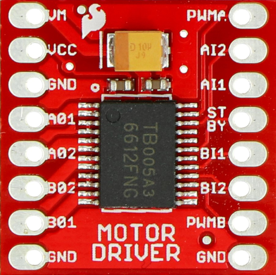
Pin Configuration and Descriptions
Below is a typical pinout for the L298N H-bridge motor driver:
| Pin Name | Description |
|---|---|
| IN1 | Input pin to control motor direction (logic HIGH or LOW). |
| IN2 | Input pin to control motor direction (logic HIGH or LOW). |
| ENA | Enable pin for motor A (connect to PWM for speed control). |
| OUT1 | Output pin connected to one terminal of motor A. |
| OUT2 | Output pin connected to the other terminal of motor A. |
| IN3 | Input pin to control motor direction for motor B (logic HIGH or LOW). |
| IN4 | Input pin to control motor direction for motor B (logic HIGH or LOW). |
| ENB | Enable pin for motor B (connect to PWM for speed control). |
| OUT3 | Output pin connected to one terminal of motor B. |
| OUT4 | Output pin connected to the other terminal of motor B. |
| VCC | Power supply for the motors (e.g., 12V). |
| GND | Ground connection. |
| 5V | Logic voltage supply (optional, depending on the model). |
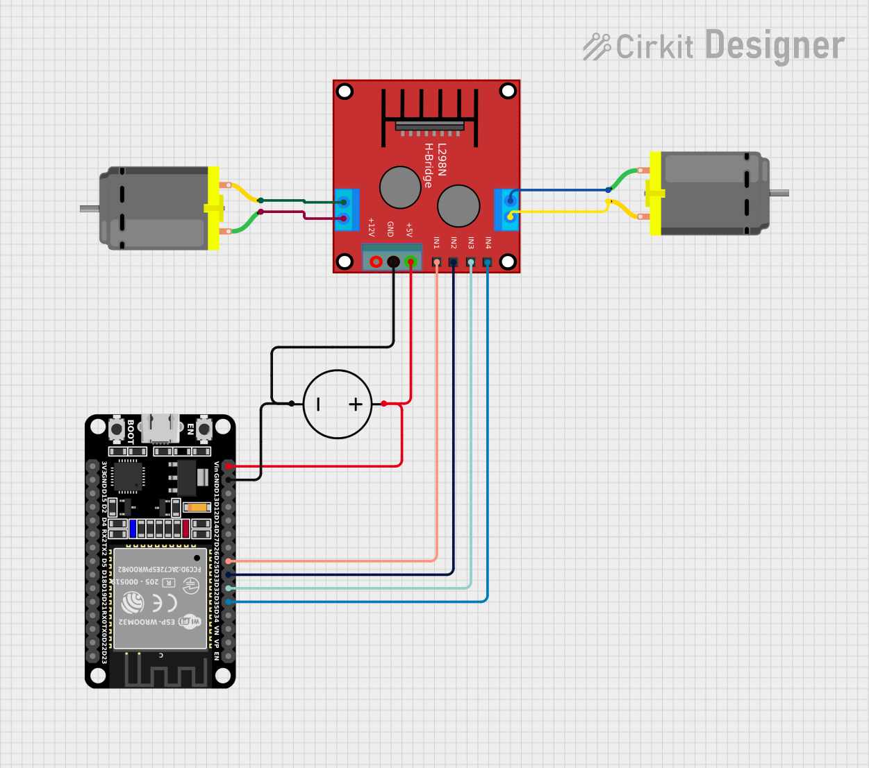
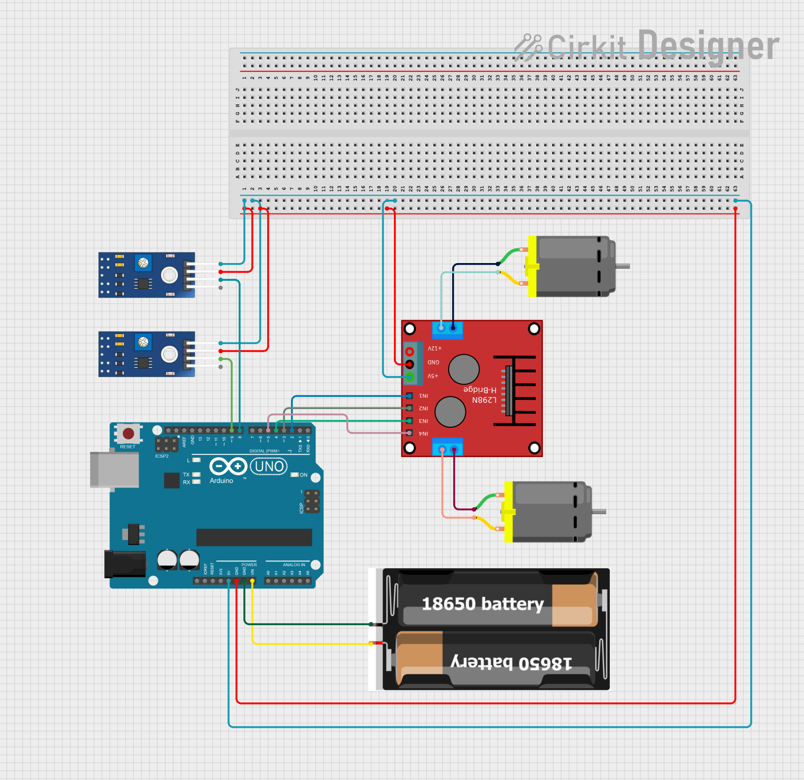
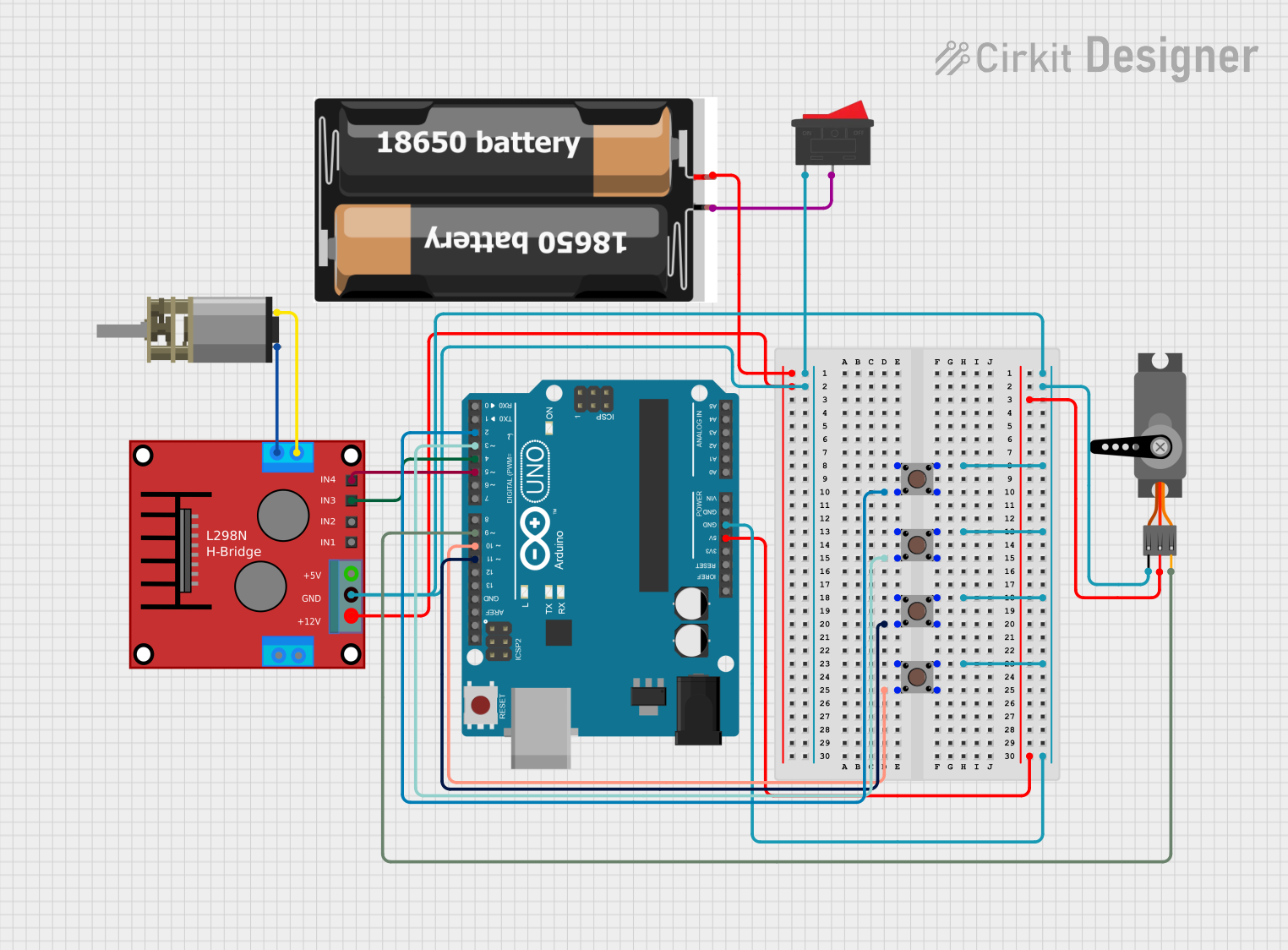
Usage Instructions
How to Use the Component in a Circuit
Power Connections:
- Connect the motor power supply to the
VCCpin and ground to theGNDpin. - If required, connect a 5V logic supply to the
5Vpin (check your specific model's datasheet).
- Connect the motor power supply to the
Motor Connections:
- Connect the motor terminals to the
OUT1andOUT2pins for motor A, orOUT3andOUT4for motor B.
- Connect the motor terminals to the
Control Pins:
- Use the
IN1andIN2pins to control the direction of motor A. - Use the
IN3andIN4pins to control the direction of motor B. - Connect the
ENAandENBpins to a PWM signal for speed control.
- Use the
Logic Control:
- Apply HIGH or LOW signals to the input pins (
IN1,IN2, etc.) to set the motor's direction. - Enable the motor by setting the
ENAorENBpin HIGH.
- Apply HIGH or LOW signals to the input pins (
Important Considerations and Best Practices
- Power Ratings: Ensure the motor driver can handle the voltage and current requirements of your motor.
- Heat Dissipation: Use a heat sink if the motor driver gets hot during operation.
- Flyback Diodes: Some H-bridge drivers include built-in diodes to protect against voltage spikes. If not, add external diodes.
- PWM Frequency: Use an appropriate PWM frequency (e.g., 1 kHz to 20 kHz) for smooth motor operation.
- Avoid Short Circuits: Never set both input pins (e.g.,
IN1andIN2) HIGH simultaneously, as this can cause a short circuit.
Example Code for Arduino UNO
Below is an example of how to control a DC motor using an L298N H-bridge motor driver with an Arduino UNO:
// Define motor control pins
const int IN1 = 7;  // Motor A direction control pin 1
const int IN2 = 8;  // Motor A direction control pin 2
const int ENA = 9;  // Motor A speed control (PWM) pin

void setup() {
  // Set motor control pins as outputs
  pinMode(IN1, OUTPUT);
  pinMode(IN2, OUTPUT);
  pinMode(ENA, OUTPUT);
}

void loop() {
  // Move motor forward
  digitalWrite(IN1, HIGH);  // Set IN1 HIGH
  digitalWrite(IN2, LOW);   // Set IN2 LOW
  analogWrite(ENA, 128);    // Set speed to 50% (PWM value: 128 out of 255)
  delay(2000);              // Run for 2 seconds

  // Stop motor
  digitalWrite(IN1, LOW);   // Set IN1 LOW
  digitalWrite(IN2, LOW);   // Set IN2 LOW
  delay(1000);              // Wait for 1 second

  // Move motor backward
  digitalWrite(IN1, LOW);   // Set IN1 LOW
  digitalWrite(IN2, HIGH);  // Set IN2 HIGH
  analogWrite(ENA, 128);    // Set speed to 50% (PWM value: 128 out of 255)
  delay(2000);              // Run for 2 seconds

  // Stop motor
  digitalWrite(IN1, LOW);   // Set IN1 LOW
  digitalWrite(IN2, LOW);   // Set IN2 LOW
  delay(1000);              // Wait for 1 second
}
Troubleshooting and FAQs
Common Issues Users Might Face
Motor Not Running:
- Check power connections to the motor driver and motor.
- Ensure the
ENAorENBpin is set HIGH or connected to a PWM signal. - Verify that the input pins (
IN1,IN2, etc.) are receiving the correct logic signals.
Motor Running in the Wrong Direction:
- Swap the logic levels of the input pins (e.g., set
IN1LOW andIN2HIGH for reverse motion).
- Swap the logic levels of the input pins (e.g., set
Overheating:
- Ensure the motor driver is not exceeding its current rating.
- Add a heat sink or cooling fan if necessary.
Noisy Motor Operation:
- Use a higher PWM frequency to reduce audible noise.
- Check for loose connections or damaged wires.
Solutions and Tips for Troubleshooting
- Use a multimeter to verify voltage levels at the motor driver pins.
- Test the motor driver with a smaller motor to ensure it is functioning correctly.
- Consult the datasheet of your specific H-bridge motor driver for detailed information on pin configurations and limitations.