How to Use Temperature Controller: Examples, Pinouts, and Specs
Introduction
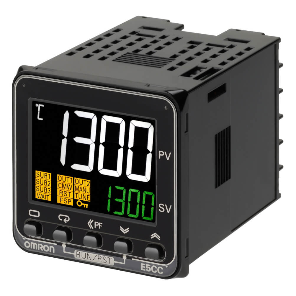
The Omron E5CC-QX3D5M-000 Temperature Controller is a sophisticated device designed to maintain a desired temperature by measuring the current temperature and adjusting heating or cooling mechanisms accordingly. This component is widely used in industrial applications, HVAC systems, and laboratory environments where precise temperature control is crucial.
Explore Projects Built with Temperature Controller
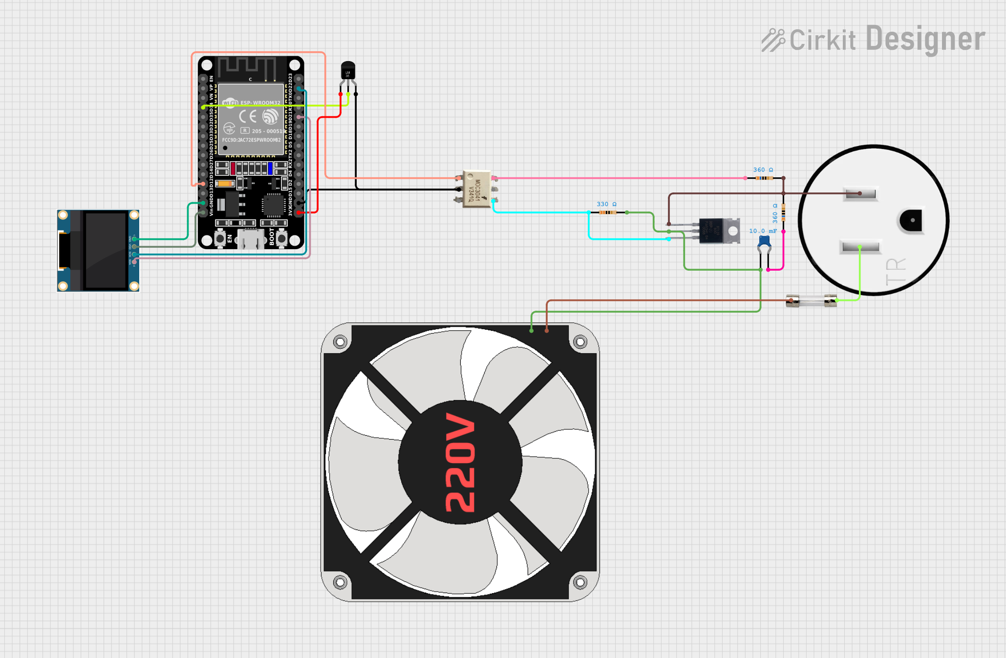

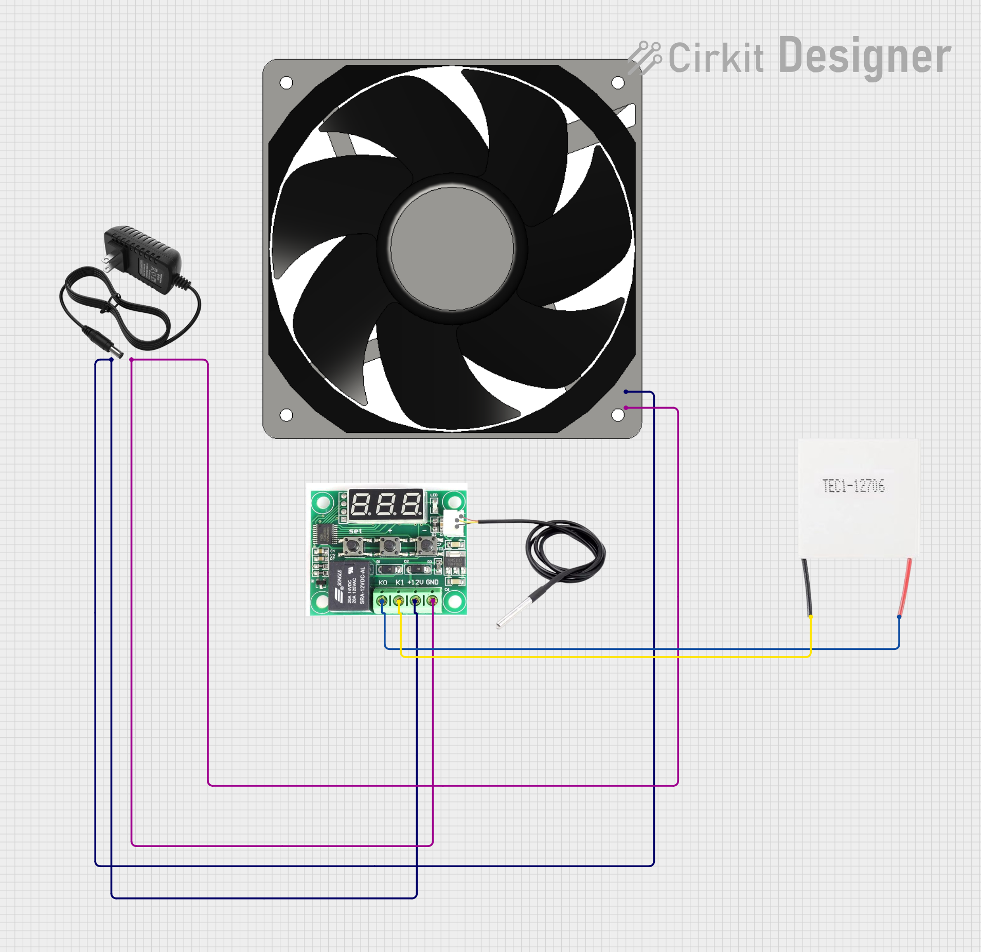

Explore Projects Built with Temperature Controller
Technical Specifications
Key Technical Details
| Parameter | Specification |
|---|---|
| Power Supply Voltage | 100 to 240 VAC |
| Power Consumption | 10 VA max |
| Control Output | Relay output |
| Input Type | Thermocouple, RTD |
| Temperature Range | -200 to 1800°C (varies by sensor) |
| Accuracy | ±0.3% of PV |
| Display | 7-segment, 4-digit display |
| Dimensions | 48 x 48 x 78 mm |
| Operating Temperature | -10 to 55°C |
| Storage Temperature | -25 to 65°C |
Pin Configuration and Descriptions
| Pin No. | Pin Name | Description |
|---|---|---|
| 1 | Power Supply | Connect to 100-240 VAC |
| 2 | Power Supply | Connect to 100-240 VAC |
| 3 | Control Output | Relay output (NO) |
| 4 | Control Output | Relay output (COM) |
| 5 | Control Output | Relay output (NC) |
| 6 | Input | Thermocouple/RTD input (+) |
| 7 | Input | Thermocouple/RTD input (-) |
| 8 | Alarm Output | Alarm relay output (NO) |
| 9 | Alarm Output | Alarm relay output (COM) |
| 10 | Alarm Output | Alarm relay output (NC) |
Usage Instructions
How to Use the Component in a Circuit
- Power Connection: Connect pins 1 and 2 to a 100-240 VAC power supply.
- Sensor Connection: Connect the thermocouple or RTD sensor to pins 6 and 7.
- Control Output: Connect the heating or cooling mechanism to pins 3, 4, and 5.
- Alarm Output: If using an alarm, connect it to pins 8, 9, and 10.
Important Considerations and Best Practices
- Sensor Type: Ensure you are using the correct sensor type (thermocouple or RTD) as per your application requirements.
- Wiring: Double-check all connections to avoid short circuits or incorrect readings.
- Calibration: Calibrate the temperature controller according to the manufacturer's instructions for accurate temperature control.
- Environment: Install the controller in an environment within the specified operating temperature range to ensure optimal performance.
Troubleshooting and FAQs
Common Issues Users Might Face
Incorrect Temperature Readings:
- Solution: Verify the sensor type and connections. Ensure the sensor is properly calibrated.
No Display or Power:
- Solution: Check the power supply connections and ensure the voltage is within the specified range.
Relay Not Activating:
- Solution: Ensure the control output connections are correct. Check if the setpoint temperature is correctly configured.
Alarm Not Triggering:
- Solution: Verify the alarm output connections and ensure the alarm setpoints are correctly configured.
Solutions and Tips for Troubleshooting
- Check Connections: Always start by checking all electrical connections for loose or incorrect wiring.
- Refer to Manual: Consult the manufacturer's manual for detailed troubleshooting steps and calibration procedures.
- Use Multimeter: Utilize a multimeter to check voltage levels and continuity in the circuit.
- Firmware Updates: Ensure the controller's firmware is up-to-date to avoid any software-related issues.
Example Code for Arduino UNO
If you are using the Omron E5CC-QX3D5M-000 Temperature Controller with an Arduino UNO, you can use the following example code to read temperature data and control a relay based on the temperature setpoint.
#include <Wire.h>

// Define the I2C address of the temperature controller
#define TEMP_CONTROLLER_ADDR 0x48

// Define the setpoint temperature
#define SETPOINT_TEMP 25.0

void setup() {
  Serial.begin(9600);
  Wire.begin();
  pinMode(8, OUTPUT); // Relay control pin
}

void loop() {
  float currentTemp = readTemperature();
  Serial.print("Current Temperature: ");
  Serial.println(currentTemp);

  if (currentTemp >= SETPOINT_TEMP) {
    digitalWrite(8, HIGH); // Turn on relay
  } else {
    digitalWrite(8, LOW); // Turn off relay
  }

  delay(1000); // Wait for 1 second
}

float readTemperature() {
  Wire.beginTransmission(TEMP_CONTROLLER_ADDR);
  Wire.write(0x00); // Command to read temperature
  Wire.endTransmission();
  Wire.requestFrom(TEMP_CONTROLLER_ADDR, 2);

  if (Wire.available() == 2) {
    int tempData = Wire.read() << 8 | Wire.read();
    return tempData * 0.1; // Convert to Celsius
  }

  return -999; // Return error value if no data
}
This code initializes the I2C communication with the temperature controller, reads the current temperature, and controls a relay based on the setpoint temperature. Ensure you have the correct I2C address and command for your specific temperature controller model.
By following this documentation, users can effectively utilize the Omron E5CC-QX3D5M-000 Temperature Controller in their applications, ensuring precise and reliable temperature control.