How to Use SIM_A7670G_PCB: Examples, Pinouts, and Specs
Introduction
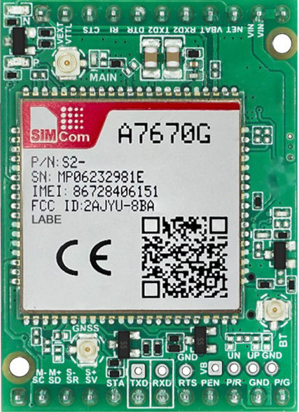
The SIM_A7670G_PCB is a printed circuit board (PCB) designed to host the SIM A7670G module, a high-performance cellular communication module manufactured by SIMCOM. This PCB facilitates seamless integration of the SIM A7670G module into IoT and M2M (Machine-to-Machine) applications, enabling connectivity through GSM, GPRS, and LTE networks. It is ideal for applications requiring reliable wireless communication, such as smart meters, asset tracking, industrial automation, and remote monitoring systems.
Explore Projects Built with SIM_A7670G_PCB


Explore Projects Built with SIM_A7670G_PCB
Common Applications and Use Cases
- IoT Devices: Enables cellular connectivity for smart devices in remote locations.
- Asset Tracking: Provides real-time location and status updates for logistics and fleet management.
- Industrial Automation: Facilitates wireless communication in industrial control systems.
- Smart Agriculture: Supports remote monitoring and control of agricultural equipment.
- Remote Monitoring: Ideal for applications like weather stations and energy meters.
Technical Specifications
Key Technical Details
| Parameter | Specification |
|---|---|
| Manufacturer | SIMCOM |
| Part ID | S2-10CVD-Z3307 |
| Supported Networks | GSM, GPRS, LTE |
| Operating Voltage | 3.3V to 4.2V |
| Power Consumption | Idle: ~1.2mA, Active: ~350mA (peak ~2A during TX burst) |
| Operating Temperature | -40°C to +85°C |
| Communication Interfaces | UART, USB, GPIO, I2C, SPI |
| Dimensions | 30mm x 30mm (PCB size) |
Pin Configuration and Descriptions
The SIM_A7670G_PCB provides a set of pins for interfacing with external devices. Below is the pin configuration:
| Pin Number | Pin Name | Description |
|---|---|---|
| 1 | VCC | Power supply input (3.3V to 4.2V) |
| 2 | GND | Ground |
| 3 | TXD | UART Transmit (data output from module) |
| 4 | RXD | UART Receive (data input to module) |
| 5 | GPIO1 | General-purpose input/output |
| 6 | GPIO2 | General-purpose input/output |
| 7 | USB_D+ | USB data positive |
| 8 | USB_D- | USB data negative |
| 9 | RESET | Reset input (active low) |
| 10 | NET_STATUS | Network status indicator (high = connected) |
| 11 | SIM_DET | SIM card detection (low = SIM present) |
| 12 | ANT | Antenna connection |
Usage Instructions
How to Use the Component in a Circuit
- Power Supply: Connect the VCC pin to a regulated power source (3.3V to 4.2V) and GND to the ground. Ensure the power source can supply sufficient current (up to 2A during transmission bursts).
- UART Communication: Connect the TXD and RXD pins to the UART pins of your microcontroller or development board (e.g., Arduino UNO). Use a logic level converter if your microcontroller operates at 5V logic.
- Antenna Connection: Attach a compatible LTE/GSM antenna to the ANT pin for optimal signal reception.
- SIM Card: Insert a valid SIM card into the SIM card slot on the PCB. Ensure the SIM card is activated and supports the required network bands.
- Reset: Use the RESET pin to restart the module if needed. Pull the pin low for at least 100ms to trigger a reset.
Important Considerations and Best Practices
- Power Supply Stability: Use a low-noise, high-current power supply to avoid voltage drops during transmission bursts.
- Antenna Placement: Position the antenna away from noise sources and metal objects to ensure strong signal reception.
- UART Baud Rate: Configure the UART baud rate to match the module's default setting (typically 115200 bps).
- Firmware Updates: Check for firmware updates from SIMCOM to ensure compatibility with the latest network standards.
Example: Connecting to an Arduino UNO
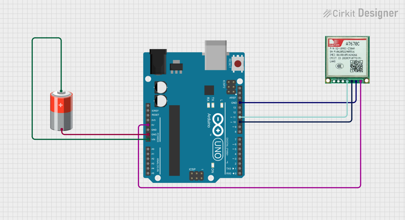
Below is an example of how to interface the SIM_A7670G_PCB with an Arduino UNO to send an SMS:
Circuit Connections
| SIM_A7670G_PCB Pin | Arduino UNO Pin |
|---|---|
| VCC | 3.3V |
| GND | GND |
| TXD | Pin 10 (RX) |
| RXD | Pin 11 (TX) |
| RESET | Pin 12 |
Arduino Code
#include <SoftwareSerial.h>

// Define RX and TX pins for SoftwareSerial
SoftwareSerial simModule(10, 11); // RX = Pin 10, TX = Pin 11

void setup() {
  // Initialize serial communication with the SIM module
  simModule.begin(115200);
  Serial.begin(9600); // For debugging with the Serial Monitor

  // Wait for the module to initialize
  Serial.println("Initializing SIM A7670G module...");
  delay(5000);

  // Send an AT command to check communication
  simModule.println("AT");
  delay(1000);
  while (simModule.available()) {
    Serial.write(simModule.read()); // Print module response to Serial Monitor
  }

  // Send an SMS
  simModule.println("AT+CMGF=1"); // Set SMS mode to text
  delay(1000);
  simModule.println("AT+CMGS=\"+1234567890\""); // Replace with recipient's number
  delay(1000);
  simModule.print("Hello from SIM A7670G!"); // SMS content
  delay(1000);
  simModule.write(26); // Send Ctrl+Z to send the SMS
}

void loop() {
  // No actions in the loop
}
Troubleshooting and FAQs
Common Issues and Solutions
Module Not Responding to AT Commands
- Cause: Incorrect UART connections or baud rate mismatch.
- Solution: Verify TXD and RXD connections. Ensure the baud rate is set to 115200 bps.
No Network Connection
- Cause: Poor signal strength or incorrect SIM card.
- Solution: Check the antenna connection and ensure the SIM card is activated and supports the required network bands.
Frequent Resets
- Cause: Insufficient power supply.
- Solution: Use a power source capable of supplying at least 2A during transmission bursts.
SIM Card Not Detected
- Cause: Faulty SIM card or improper insertion.
- Solution: Reinsert the SIM card and ensure it is properly seated in the slot.
FAQs
Q: Can the SIM_A7670G_PCB operate on 5V?
A: No, the module requires a power supply between 3.3V and 4.2V. Use a voltage regulator if needed.Q: What is the maximum data rate supported?
A: The SIM A7670G module supports LTE Cat-M1 and NB-IoT with data rates up to 375 kbps.Q: How do I update the firmware?
A: Firmware updates can be performed via the USB interface using SIMCOM's official tools.Q: Can I use this module for voice calls?
A: Yes, the SIM A7670G supports voice calls over GSM networks.
This concludes the documentation for the SIM_A7670G_PCB. For further assistance, refer to the official SIMCOM datasheet or contact technical support.