
How to Use Wemos D1 : Examples, Pinouts, and Specs
 Design with Wemos D1 in Cirkit Designer
Introduction
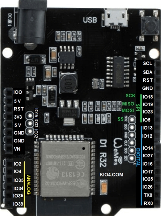
The Wemos D1, part number D1 R32, is a microcontroller board developed by Wemos. It is based on the ESP8266 Wi-Fi module and is specifically designed for Internet of Things (IoT) applications. The board combines the power of the ESP8266 with the ease of use of an Arduino-compatible form factor, making it an excellent choice for both beginners and experienced developers.
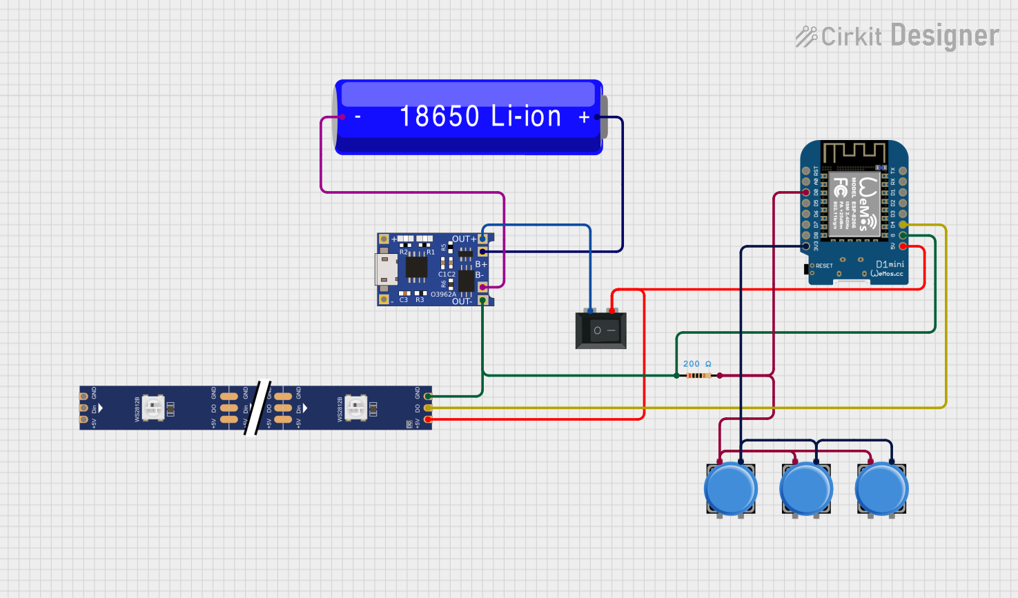
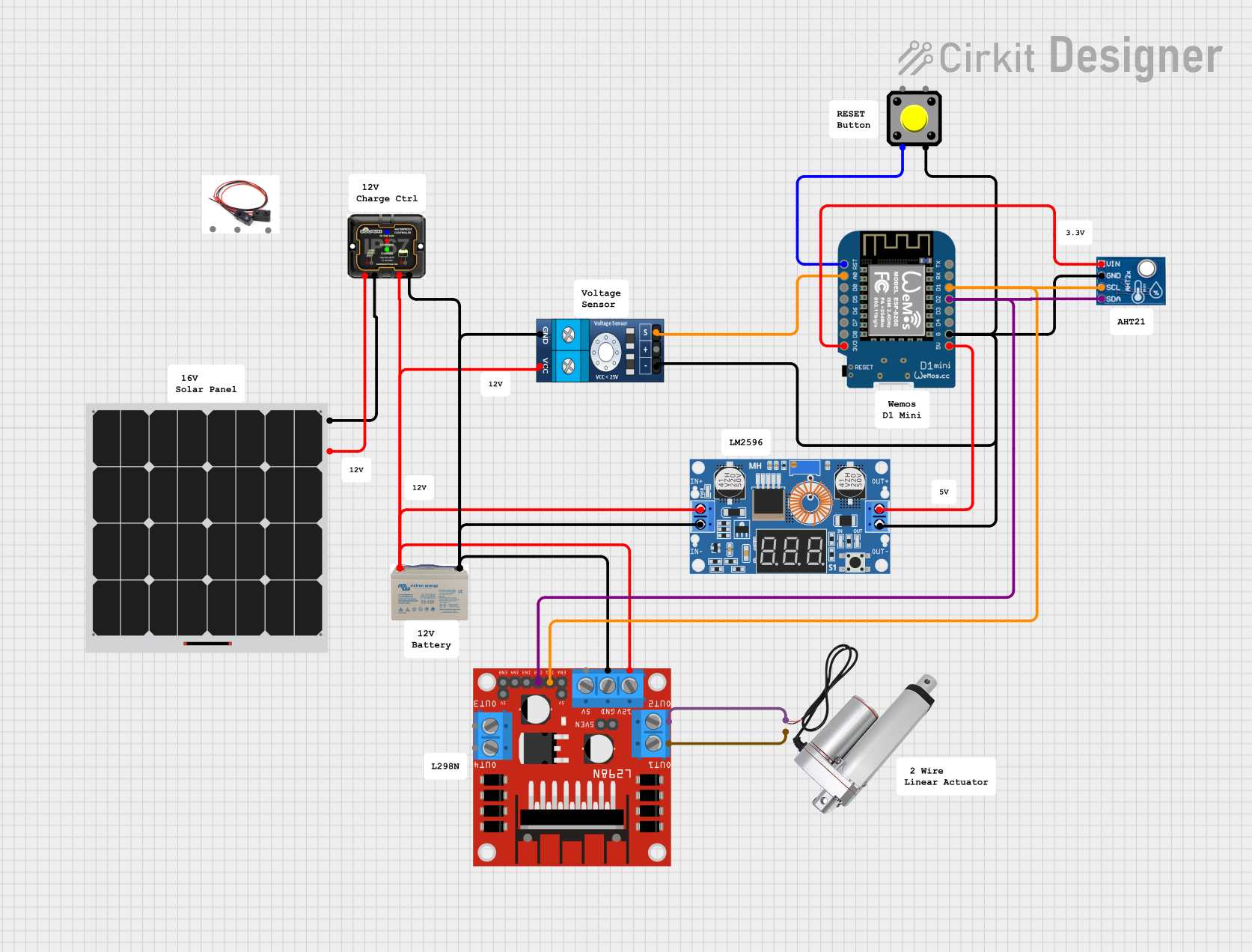
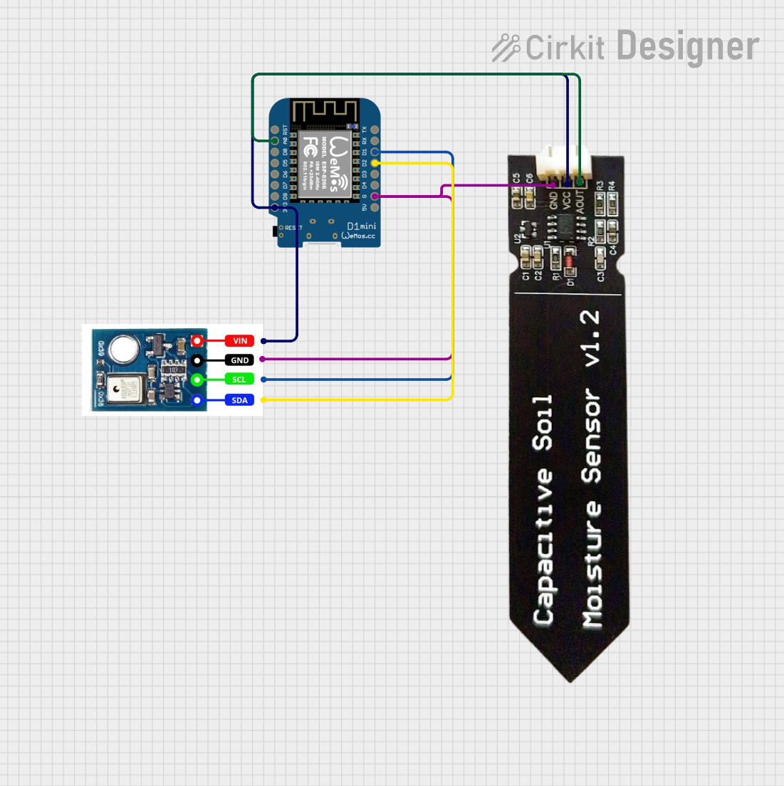
Explore Projects Built with Wemos D1
 Open Project in Cirkit Designer
 Open Project in Cirkit Designer
 Open Project in Cirkit Designer
 Open Project in Cirkit Designer
Explore Projects Built with Wemos D1
Open Project in Cirkit DesignerOpen Project in Cirkit DesignerOpen Project in Cirkit DesignerOpen Project in Cirkit DesignerCommon Applications and Use Cases
- Home automation systems
- Wireless sensor networks
- IoT prototyping and development
- Remote monitoring and control
- Smart appliances and devices
- Educational projects and learning platforms
Technical Specifications
The Wemos D1 offers a range of features and capabilities that make it versatile for various IoT applications. Below are the key technical specifications:
| Specification | Details |
|---|---|
| Microcontroller | ESP8266 (Tensilica L106 32-bit RISC processor, clocked at 80/160 MHz) |
| Flash Memory | 4 MB (32 Mbit) |
| Operating Voltage | 3.3V |
| Input Voltage (VIN) | 7-12V (via barrel jack) or 5V (via USB) |
| Digital I/O Pins | 11 |
| Analog Input Pins | 1 (10-bit ADC, 0-3.3V range) |
| Wi-Fi | IEEE 802.11 b/g/n, integrated TCP/IP stack |
| USB Interface | Micro-USB for programming and power supply |
| Communication Protocols | UART, SPI, I2C |
| Dimensions | 68.6mm x 53.4mm |
Pin Configuration and Descriptions
The Wemos D1 pinout is similar to that of an Arduino UNO, but with some differences due to the ESP8266 architecture. Below is the pin configuration:
| Pin | Label | Description |
|---|---|---|
| 1 | VIN | Input voltage (7-12V) for powering the board |
| 2 | 3V3 | 3.3V output from the onboard voltage regulator |
| 3 | GND | Ground pin |
| 4 | D0-D8 | Digital I/O pins (GPIO pins of the ESP8266) |
| 5 | A0 | Analog input pin (0-3.3V range) |
| 6 | RX | UART receive pin |
| 7 | TX | UART transmit pin |
| 8 | RST | Reset pin |
| 9 | EN | Enable pin (active high, used to enable/disable the ESP8266 module) |
Usage Instructions
The Wemos D1 is easy to use and can be programmed using the Arduino IDE or other compatible development environments. Below are the steps to get started:
Step 1: Setting Up the Arduino IDE
- Download and install the Arduino IDE from the official website.
- Open the Arduino IDE and go to File > Preferences.
- In the "Additional Board Manager URLs" field, add the following URL:
http://arduino.esp8266.com/stable/package_esp8266com_index.json - Go to Tools > Board > Boards Manager, search for "ESP8266," and install the package.
Step 2: Connecting the Wemos D1
- Connect the Wemos D1 to your computer using a micro-USB cable.
- In the Arduino IDE, go to Tools > Board and select "LOLIN(WEMOS) D1 R2 & mini."
- Select the appropriate COM port under Tools > Port.
Step 3: Writing and Uploading Code
Here is an example code to blink an LED connected to pin D4:
// Example: Blink an LED on Wemos D1
// This code blinks an LED connected to pin D4 every second.

void setup() {
  pinMode(D4, OUTPUT); // Set pin D4 as an output
}

void loop() {
  digitalWrite(D4, HIGH); // Turn the LED on
  delay(1000);            // Wait for 1 second
  digitalWrite(D4, LOW);  // Turn the LED off
  delay(1000);            // Wait for 1 second
}
Important Considerations and Best Practices
- Voltage Levels: The Wemos D1 operates at 3.3V logic levels. Ensure that any external components connected to the GPIO pins are compatible with 3.3V.
- Power Supply: Use a stable power source to avoid unexpected resets or instability.
- Wi-Fi Configuration: When using Wi-Fi, ensure that your network credentials are correctly configured in the code.
Troubleshooting and FAQs
Common Issues and Solutions
Problem: The board is not detected by the Arduino IDE.
- Solution: Ensure that the correct USB drivers are installed. For Windows, you may need to install the CH340 driver.
Problem: Uploading code fails with a timeout error.
- Solution: Check that the correct board and COM port are selected in the Arduino IDE. Also, ensure that no other application is using the COM port.
Problem: The board resets unexpectedly during operation.
- Solution: Verify that the power supply is stable and capable of providing sufficient current (at least 500mA).
Problem: Wi-Fi connection fails.
- Solution: Double-check the SSID and password in your code. Ensure that the Wi-Fi network is within range and not using unsupported security protocols.
FAQs
Q: Can I use 5V sensors with the Wemos D1?
A: No, the GPIO pins operate at 3.3V. Use a level shifter if you need to interface with 5V sensors.Q: How do I reset the board?
A: Press the RST button on the board to perform a hardware reset.Q: Can I power the board using a battery?
A: Yes, you can power the board using a 7-12V battery connected to the VIN pin or a 3.7V LiPo battery with a suitable voltage regulator.
This concludes the documentation for the Wemos D1. For further assistance, refer to the official Wemos documentation or community forums.