How to Use lcd 20*4: Examples, Pinouts, and Specs
Introduction
A 20x4 LCD (Liquid Crystal Display) is a versatile display module capable of showing 20 characters per line across 4 lines. It is widely used in embedded systems for displaying text, numeric data, and simple graphics. The module operates using either a parallel or serial interface, making it compatible with a variety of microcontrollers, including Arduino, Raspberry Pi, and other development boards.
Explore Projects Built with lcd 20*4

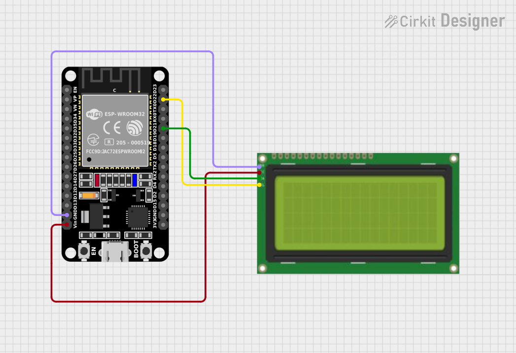
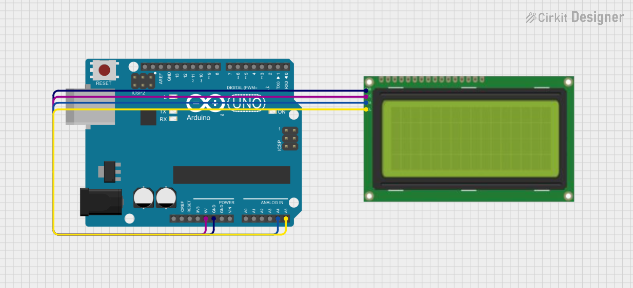
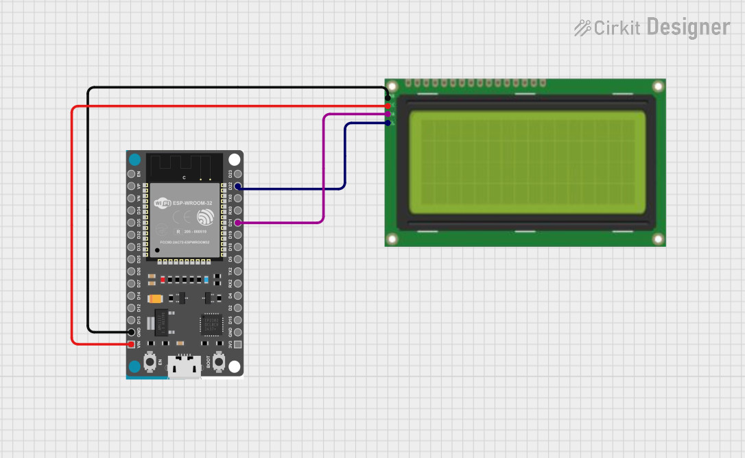
Explore Projects Built with lcd 20*4
Common Applications and Use Cases
- User interfaces for embedded systems
- Displaying sensor data in IoT projects
- Menu systems for control panels
- Educational and prototyping purposes
- Industrial automation displays
Technical Specifications
The following table outlines the key technical details of the LCD 20x4 module:
| Parameter | Specification |
|---|---|
| Display Type | 20 characters x 4 lines |
| Operating Voltage | 4.7V to 5.3V |
| Operating Current | 1.5mA (without backlight) |
| Backlight Voltage | 4.2V to 4.6V |
| Backlight Current | 120mA (typical) |
| Interface Type | Parallel (4-bit or 8-bit) or I2C |
| Character Size | 5x8 dot matrix |
| Operating Temperature | -20°C to +70°C |
| Storage Temperature | -30°C to +80°C |
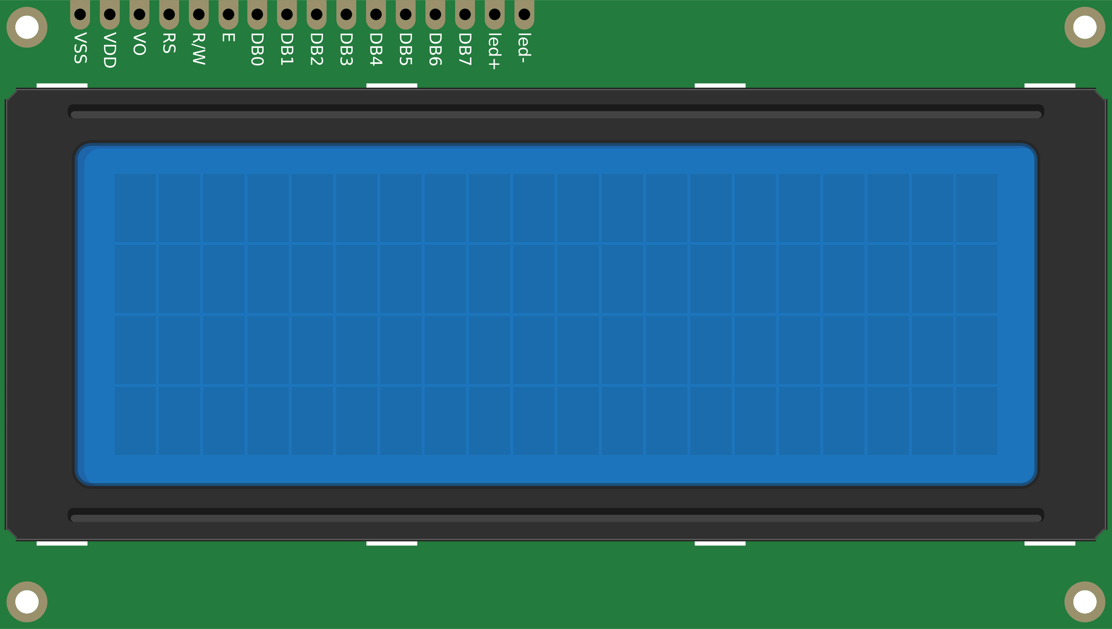
Pin Configuration and Descriptions
The LCD 20x4 module typically has 16 pins for parallel communication. If using an I2C adapter, only 4 pins are required. Below is the pin configuration for the parallel interface:
| Pin | Name | Description |
|---|---|---|
| 1 | VSS | Ground (0V) |
| 2 | VDD | Power supply (4.7V to 5.3V) |
| 3 | VO | Contrast adjustment (connect to a potentiometer) |
| 4 | RS | Register Select (0: Command, 1: Data) |
| 5 | RW | Read/Write (0: Write, 1: Read) |
| 6 | E | Enable signal (starts data read/write) |
| 7-14 | D0-D7 | Data pins (used for 4-bit or 8-bit communication) |
| 15 | LED+ | Backlight anode (connect to +5V via a resistor if needed) |
| 16 | LED- | Backlight cathode (connect to ground) |
For I2C communication (with an adapter), the pin configuration is as follows:
| Pin | Name | Description |
|---|---|---|
| 1 | GND | Ground (0V) |
| 2 | VCC | Power supply (4.7V to 5.3V) |
| 3 | SDA | Serial Data Line |
| 4 | SCL | Serial Clock Line |
Usage Instructions
How to Use the LCD 20x4 in a Circuit
- Power the LCD: Connect the VSS pin to ground and the VDD pin to a 5V power source.
- Adjust Contrast: Connect the VO pin to the middle terminal of a 10kΩ potentiometer. Connect the other two terminals of the potentiometer to VDD and GND.
- Interface Selection:
- For parallel communication, connect the RS, RW, E, and data pins (D4-D7 for 4-bit mode or D0-D7 for 8-bit mode) to the microcontroller.
- For I2C communication, connect the SDA and SCL pins to the corresponding pins on the microcontroller.
- Backlight: Connect the LED+ pin to 5V (via a resistor if needed) and the LED- pin to ground.
- Initialize the LCD: Use the appropriate library or commands to initialize the LCD and configure it for 4-bit, 8-bit, or I2C mode.
Important Considerations and Best Practices
- Power Supply: Ensure a stable 5V power supply to avoid flickering or malfunction.
- Contrast Adjustment: Use a potentiometer to fine-tune the contrast for optimal visibility.
- Backlight Control: Use a current-limiting resistor if the backlight is too bright or to prevent damage.
- Library Support: For Arduino, use the
LiquidCrystallibrary for parallel communication or theLiquidCrystal_I2Clibrary for I2C communication. - I2C Address: If using an I2C adapter, note the default I2C address (commonly
0x27or0x3F) and adjust it in the code if necessary.
Example Code for Arduino (I2C Interface)
#include <Wire.h>
#include <LiquidCrystal_I2C.h>

// Initialize the LCD with I2C address 0x27 and dimensions 20x4
LiquidCrystal_I2C lcd(0x27, 20, 4);

void setup() {
  lcd.init(); // Initialize the LCD
  lcd.backlight(); // Turn on the backlight

  // Display a welcome message
  lcd.setCursor(0, 0); // Set cursor to column 0, row 0
  lcd.print("Hello, World!"); // Print text on the first line
  lcd.setCursor(0, 1); // Set cursor to column 0, row 1
  lcd.print("LCD 20x4 Demo"); // Print text on the second line
}

void loop() {
  // Example: Display a counter on the third line
  static int counter = 0;
  lcd.setCursor(0, 2); // Set cursor to column 0, row 2
  lcd.print("Counter: ");
  lcd.print(counter++); // Increment and display the counter
  delay(1000); // Wait for 1 second
}
Troubleshooting and FAQs
Common Issues and Solutions
No Display or Blank Screen:
- Check the power connections (VSS, VDD) and ensure the LCD is receiving 5V.
- Adjust the contrast using the potentiometer connected to the VO pin.
- Verify the initialization code and ensure the correct communication mode is selected.
Flickering or Unstable Display:
- Ensure a stable power supply and proper grounding.
- Check for loose or faulty connections in the circuit.
Incorrect Characters or No Response:
- Verify the wiring of the data pins (D4-D7 for 4-bit mode or D0-D7 for 8-bit mode).
- For I2C, confirm the correct I2C address and ensure the SDA and SCL lines are properly connected.
Backlight Not Working:
- Check the LED+ and LED- connections.
- Use a current-limiting resistor if the backlight is too dim or not functioning.
FAQs
Q: Can I use the LCD 20x4 with a 3.3V microcontroller?
A: The LCD itself requires 5V for operation. However, you can use a level shifter to interface it with a 3.3V microcontroller.
Q: How do I find the I2C address of my LCD module?
A: Use an I2C scanner sketch on your microcontroller to detect the address. The default is often 0x27 or 0x3F.
Q: Can I display custom characters on the LCD?
A: Yes, the LCD supports custom characters. Use the createChar() function in the Arduino LiquidCrystal or LiquidCrystal_I2C library to define and display custom characters.
Q: What is the maximum cable length for I2C communication?
A: The maximum length depends on the pull-up resistors and communication speed, but it is typically limited to 1 meter for reliable operation.