Cirkit Designer Logo
Cirkit Designer
Your all-in-one circuit design IDE
Home / 
Component Documentation

How to Use GY4725: Examples, Pinouts, and Specs

Image of GY4725
Cirkit Designer LogoDesign with GY4725 in Cirkit Designer

Introduction

The GY4725 is a high-precision digital gyroscope sensor designed to measure angular velocity. Manufactured by "No Name" with the part ID "DAC (Digital to Analog Converter)," this component is widely used in applications requiring accurate orientation and motion tracking. Its compact design and reliable performance make it ideal for robotics, drones, gaming devices, and other motion-sensitive systems.

Explore Projects Built with GY4725

Use Cirkit Designer to design, explore, and prototype these projects online. Some projects support real-time simulation. Click "Open Project" to start designing instantly!
Battery-Powered Emergency Alert System with NUCLEO-F072RB, SIM800L, and GPS NEO 6M
Image of women safety: A project utilizing GY4725 in a practical application
This circuit is an emergency alert system that uses a NUCLEO-F072RB microcontroller to send SMS alerts and make calls via a SIM800L GSM module, while obtaining location data from a GPS NEO 6M module. The system is powered by a Li-ion battery and includes a TP4056 module for battery charging and protection, with a rocker switch to control power to the microcontroller.
Cirkit Designer LogoOpen Project in Cirkit Designer
Arduino Mega 2560 Based Security System with Fingerprint Authentication and SMS Alerts
Image of Door security system: A project utilizing GY4725 in a practical application
This circuit features an Arduino Mega 2560 microcontroller interfaced with a SIM800L GSM module, two fingerprint scanners, an I2C LCD display, an IR sensor, and a piezo buzzer. Power management is handled by a PowerBoost 1000 Basic Pad USB, a TP4056 charging module, and a Li-ion 18650 battery, with an option to use a Mini AC-DC 110V-230V to 5V 700mA module for direct power supply. The primary functionality appears to be a security system with GSM communication capabilities, biometric access control, and visual/audible feedback.
Cirkit Designer LogoOpen Project in Cirkit Designer
Cellular-Enabled IoT Device with Real-Time Clock and Power Management
Image of LRCM PHASE 2 BASIC: A project utilizing GY4725 in a practical application
This circuit features a LilyGo-SIM7000G module for cellular communication and GPS functionality, interfaced with an RTC DS3231 for real-time clock capabilities. It includes voltage sensing through two voltage sensor modules, and uses an 8-channel opto-coupler for isolating different parts of the circuit. Power management is handled by a buck converter connected to a DC power source and batteries, with a fuse for protection and a rocker switch for on/off control. Additionally, there's an LED for indication purposes.
Cirkit Designer LogoOpen Project in Cirkit Designer
Bluetooth-Controlled Multi-Function Arduino Nano Gadget
Image of Copy of Smarttt: A project utilizing GY4725 in a practical application
This is a portable, microcontroller-driven interactive device featuring Bluetooth connectivity, visual (RGB LED), auditory (loudspeaker), and haptic (vibration motor) feedback, user input (pushbutton), and a rechargeable power system (TP4056 with Li-ion battery).
Cirkit Designer LogoOpen Project in Cirkit Designer

Explore Projects Built with GY4725

Use Cirkit Designer to design, explore, and prototype these projects online. Some projects support real-time simulation. Click "Open Project" to start designing instantly!
Image of women safety: A project utilizing GY4725 in a practical application
Battery-Powered Emergency Alert System with NUCLEO-F072RB, SIM800L, and GPS NEO 6M
This circuit is an emergency alert system that uses a NUCLEO-F072RB microcontroller to send SMS alerts and make calls via a SIM800L GSM module, while obtaining location data from a GPS NEO 6M module. The system is powered by a Li-ion battery and includes a TP4056 module for battery charging and protection, with a rocker switch to control power to the microcontroller.
Cirkit Designer LogoOpen Project in Cirkit Designer
Image of Door security system: A project utilizing GY4725 in a practical application
Arduino Mega 2560 Based Security System with Fingerprint Authentication and SMS Alerts
This circuit features an Arduino Mega 2560 microcontroller interfaced with a SIM800L GSM module, two fingerprint scanners, an I2C LCD display, an IR sensor, and a piezo buzzer. Power management is handled by a PowerBoost 1000 Basic Pad USB, a TP4056 charging module, and a Li-ion 18650 battery, with an option to use a Mini AC-DC 110V-230V to 5V 700mA module for direct power supply. The primary functionality appears to be a security system with GSM communication capabilities, biometric access control, and visual/audible feedback.
Cirkit Designer LogoOpen Project in Cirkit Designer
Image of LRCM PHASE 2 BASIC: A project utilizing GY4725 in a practical application
Cellular-Enabled IoT Device with Real-Time Clock and Power Management
This circuit features a LilyGo-SIM7000G module for cellular communication and GPS functionality, interfaced with an RTC DS3231 for real-time clock capabilities. It includes voltage sensing through two voltage sensor modules, and uses an 8-channel opto-coupler for isolating different parts of the circuit. Power management is handled by a buck converter connected to a DC power source and batteries, with a fuse for protection and a rocker switch for on/off control. Additionally, there's an LED for indication purposes.
Cirkit Designer LogoOpen Project in Cirkit Designer
Image of Copy of Smarttt: A project utilizing GY4725 in a practical application
Bluetooth-Controlled Multi-Function Arduino Nano Gadget
This is a portable, microcontroller-driven interactive device featuring Bluetooth connectivity, visual (RGB LED), auditory (loudspeaker), and haptic (vibration motor) feedback, user input (pushbutton), and a rechargeable power system (TP4056 with Li-ion battery).
Cirkit Designer LogoOpen Project in Cirkit Designer

Common Applications:

  • Robotics for precise movement control
  • Drones for stabilization and navigation
  • Motion tracking in gaming and virtual reality systems
  • Industrial equipment for monitoring rotational motion
  • Automotive systems for stability control

Technical Specifications

The GY4725 is a versatile and efficient gyroscope sensor with the following key specifications:

Parameter Value
Supply Voltage 3.3V to 5V
Communication Protocol I2C
Angular Velocity Range ±250°/s, ±500°/s, ±1000°/s, ±2000°/s
Resolution 16-bit
Operating Temperature -40°C to +85°C
Power Consumption Low power mode: 3.6 mA
Dimensions 15mm x 15mm x 3mm

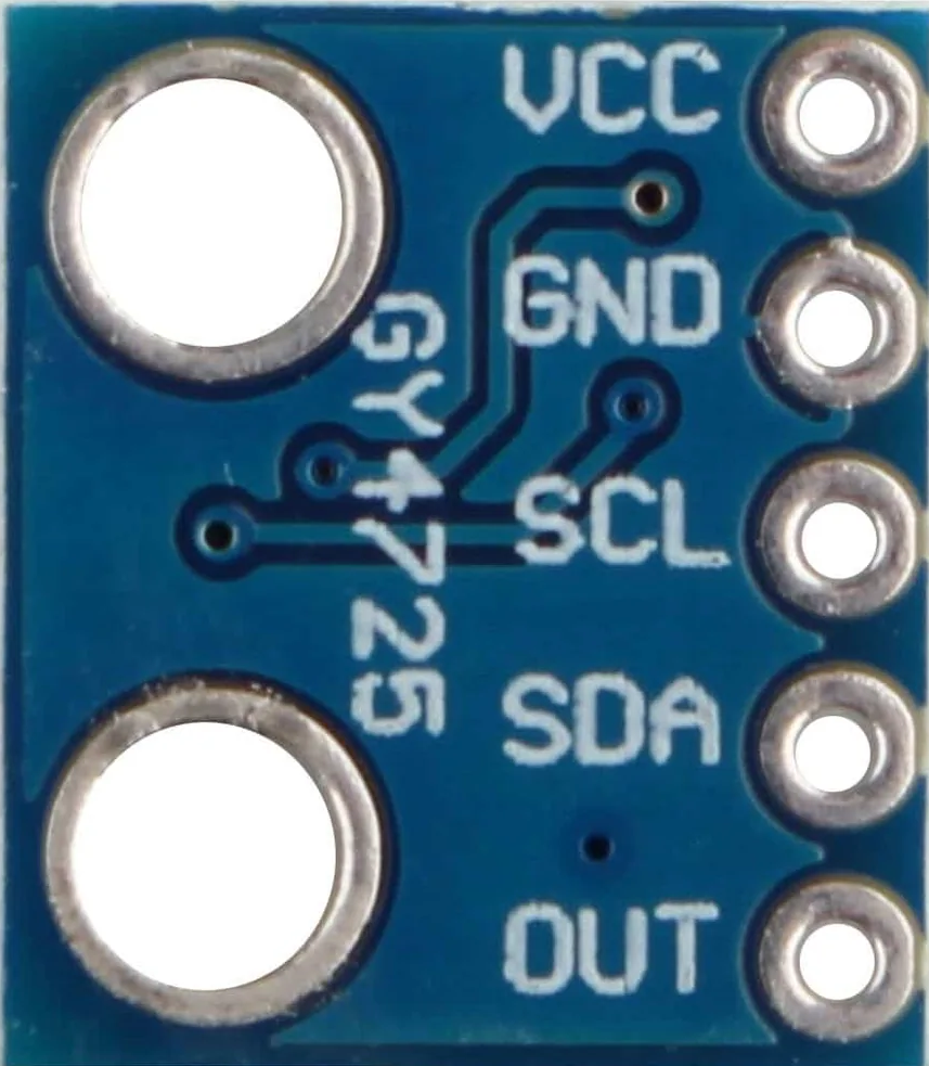
Pin Configuration and Descriptions

The GY4725 has a standard 4-pin interface for easy integration into circuits. Below is the pinout description:

Pin Name Description
1 VCC Power supply input (3.3V to 5V)
2 GND Ground connection
3 SDA I2C data line for communication
4 SCL I2C clock line for communication

Usage Instructions

How to Use the GY4725 in a Circuit

  1. Power Supply: Connect the VCC pin to a 3.3V or 5V power source and the GND pin to the ground.
  2. I2C Communication: Connect the SDA and SCL pins to the corresponding I2C pins on your microcontroller (e.g., Arduino UNO).
  3. Pull-Up Resistors: Use 4.7kΩ pull-up resistors on the SDA and SCL lines if not already present on your board.
  4. Initialization: Configure the gyroscope's settings (e.g., angular velocity range) via I2C commands.

Important Considerations and Best Practices

  • Ensure the power supply voltage matches the component's requirements to avoid damage.
  • Place the sensor on a stable surface to minimize vibrations and improve accuracy.
  • Use proper decoupling capacitors near the power pins to reduce noise.
  • Calibrate the sensor before use to account for any offsets or drift.

Example Code for Arduino UNO

Below is an example of how to interface the GY4725 with an Arduino UNO using the I2C protocol:

#include <Wire.h> // Include the Wire library for I2C communication

#define GY4725_ADDRESS 0x68 // Default I2C address of the GY4725

void setup() {
  Wire.begin(); // Initialize I2C communication
  Serial.begin(9600); // Start serial communication for debugging

  // Initialize the GY4725
  Wire.beginTransmission(GY4725_ADDRESS);
  Wire.write(0x6B); // Access the power management register
  Wire.write(0x00); // Wake up the sensor
  Wire.endTransmission();

  Serial.println("GY4725 Initialized");
}

void loop() {
  int16_t gyroX, gyroY, gyroZ;

  // Request 6 bytes of data from the GY4725
  Wire.beginTransmission(GY4725_ADDRESS);
  Wire.write(0x43); // Starting register for gyroscope data
  Wire.endTransmission(false);
  Wire.requestFrom(GY4725_ADDRESS, 6, true);

  // Read the gyroscope data
  gyroX = (Wire.read() << 8) | Wire.read(); // Combine high and low bytes
  gyroY = (Wire.read() << 8) | Wire.read();
  gyroZ = (Wire.read() << 8) | Wire.read();

  // Print the angular velocity values
  Serial.print("Gyro X: ");
  Serial.print(gyroX);
  Serial.print(" | Gyro Y: ");
  Serial.print(gyroY);
  Serial.print(" | Gyro Z: ");
  Serial.println(gyroZ);

  delay(500); // Delay for readability
}

Troubleshooting and FAQs

Common Issues and Solutions

  1. No Data Output:

    • Ensure the SDA and SCL lines are correctly connected to the microcontroller.
    • Verify that the I2C address (default: 0x68) matches the sensor's configuration.
  2. Incorrect Readings:

    • Calibrate the sensor to eliminate offsets or drift.
    • Check for vibrations or unstable mounting that may affect accuracy.
  3. Communication Errors:

    • Use pull-up resistors on the SDA and SCL lines if not already present.
    • Ensure the I2C clock speed is compatible with the sensor (typically 100kHz or 400kHz).

FAQs

Q: Can the GY4725 operate at 5V?
A: Yes, the GY4725 supports a supply voltage range of 3.3V to 5V.

Q: How do I change the angular velocity range?
A: The angular velocity range can be configured by writing to the appropriate register via I2C. Refer to the sensor's datasheet for detailed instructions.

Q: Is the GY4725 compatible with Raspberry Pi?
A: Yes, the GY4725 can be used with Raspberry Pi via the I2C interface.

Q: Do I need to calibrate the sensor?
A: Calibration is recommended to improve accuracy and account for environmental factors or sensor drift.

This documentation provides a comprehensive guide to using the GY4725 gyroscope sensor effectively in your projects.