Cirkit Designer Logo
Cirkit Designer
Your all-in-one circuit design IDE
Home / 
Component Documentation

How to Use DHT11 Sensor V2: Examples, Pinouts, and Specs

Image of DHT11 Sensor V2
Cirkit Designer LogoDesign with DHT11 Sensor V2 in Cirkit Designer

Introduction

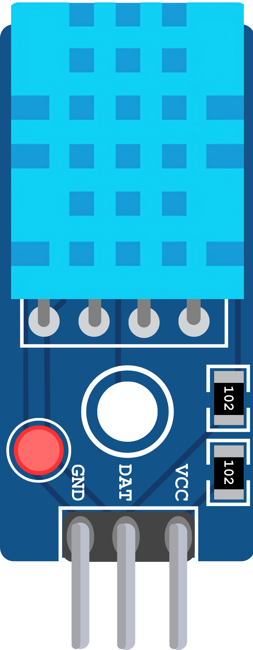
The DHT11 Sensor V2 is a low-cost, digital temperature and humidity sensor that provides reliable readings for environmental monitoring. It is widely used in various applications such as weather stations, home automation systems, and HVAC control. The sensor is known for its ease of use and is particularly popular among hobbyists and educators for use in small projects.

Explore Projects Built with DHT11 Sensor V2

Use Cirkit Designer to design, explore, and prototype these projects online. Some projects support real-time simulation. Click "Open Project" to start designing instantly!
Arduino Mega 2560 with Multiple DHT Sensors for Environmental Monitoring
Image of Schematic Diagram: A project utilizing DHT11 Sensor V2 in a practical application
This circuit is designed to monitor temperature and humidity using two DHT22 sensors and one DHT11 sensor, all controlled by an Arduino Mega 2560. The sensors are powered by the Arduino and communicate with it through digital pins D2, D3, and D4. The provided code is a template for implementing the sensor data acquisition logic.
Cirkit Designer LogoOpen Project in Cirkit Designer
Arduino UNO Based DHT11 Temperature and Humidity Monitoring System
Image of Measure Temperature a: A project utilizing DHT11 Sensor V2 in a practical application
This circuit connects a DHT11 Humidity and Temperature Sensor to an Arduino UNO microcontroller. The sensor's VDD pin is connected to the 5V output of the Arduino through a 10k Ohm resistor, its DATA pin is connected to digital pin 2 (D2) on the Arduino, and its GND pin is connected to the Arduino's ground. The Arduino is programmed to read temperature and humidity data from the DHT11 sensor and output the readings to the serial monitor.
Cirkit Designer LogoOpen Project in Cirkit Designer
Arduino and ESP8266 Based Environmental Monitoring System with LoRa Communication
Image of MP50: A project utilizing DHT11 Sensor V2 in a practical application
This circuit is a multi-sensor data acquisition system with wireless communication capabilities. It uses an Arduino 101 to interface with a DHT11 temperature and humidity sensor, an MQ2 gas sensor, a flow rate sensor, and a PH meter. The data collected from these sensors is transmitted via a LoRa Ra-02 SX1278 module, and the system can also communicate with an ESP8266 module for additional wireless functionality.
Cirkit Designer LogoOpen Project in Cirkit Designer
NodeMCU ESP8266 with DHT11 and MQ Gas Sensors for Environmental Monitoring
Image of air quality monitoring: A project utilizing DHT11 Sensor V2 in a practical application
This circuit features a NodeMCU V3 ESP8266 microcontroller interfaced with an array of sensors for environmental monitoring. The KY-015 DHT11 sensor is connected for temperature and humidity readings, while the MQ-2 and MQ135 sensors are used for detecting various gases and air quality. The NodeMCU reads analog and digital signals from these sensors to process and potentially transmit environmental data.
Cirkit Designer LogoOpen Project in Cirkit Designer

Explore Projects Built with DHT11 Sensor V2

Use Cirkit Designer to design, explore, and prototype these projects online. Some projects support real-time simulation. Click "Open Project" to start designing instantly!
Image of Schematic Diagram: A project utilizing DHT11 Sensor V2 in a practical application
Arduino Mega 2560 with Multiple DHT Sensors for Environmental Monitoring
This circuit is designed to monitor temperature and humidity using two DHT22 sensors and one DHT11 sensor, all controlled by an Arduino Mega 2560. The sensors are powered by the Arduino and communicate with it through digital pins D2, D3, and D4. The provided code is a template for implementing the sensor data acquisition logic.
Cirkit Designer LogoOpen Project in Cirkit Designer
Image of Measure Temperature a: A project utilizing DHT11 Sensor V2 in a practical application
Arduino UNO Based DHT11 Temperature and Humidity Monitoring System
This circuit connects a DHT11 Humidity and Temperature Sensor to an Arduino UNO microcontroller. The sensor's VDD pin is connected to the 5V output of the Arduino through a 10k Ohm resistor, its DATA pin is connected to digital pin 2 (D2) on the Arduino, and its GND pin is connected to the Arduino's ground. The Arduino is programmed to read temperature and humidity data from the DHT11 sensor and output the readings to the serial monitor.
Cirkit Designer LogoOpen Project in Cirkit Designer
Image of MP50: A project utilizing DHT11 Sensor V2 in a practical application
Arduino and ESP8266 Based Environmental Monitoring System with LoRa Communication
This circuit is a multi-sensor data acquisition system with wireless communication capabilities. It uses an Arduino 101 to interface with a DHT11 temperature and humidity sensor, an MQ2 gas sensor, a flow rate sensor, and a PH meter. The data collected from these sensors is transmitted via a LoRa Ra-02 SX1278 module, and the system can also communicate with an ESP8266 module for additional wireless functionality.
Cirkit Designer LogoOpen Project in Cirkit Designer
Image of air quality monitoring: A project utilizing DHT11 Sensor V2 in a practical application
NodeMCU ESP8266 with DHT11 and MQ Gas Sensors for Environmental Monitoring
This circuit features a NodeMCU V3 ESP8266 microcontroller interfaced with an array of sensors for environmental monitoring. The KY-015 DHT11 sensor is connected for temperature and humidity readings, while the MQ-2 and MQ135 sensors are used for detecting various gases and air quality. The NodeMCU reads analog and digital signals from these sensors to process and potentially transmit environmental data.
Cirkit Designer LogoOpen Project in Cirkit Designer

Technical Specifications

Key Technical Details

  • Voltage: 3.3 to 5V DC
  • Current: 2.5mA max use of current during conversion (while requesting data)
  • Humidity: 20-80% with 5% accuracy
  • Temperature: 0-50°C with ±2°C accuracy
  • Sampling Rate: No more than 1 Hz (once every second)
  • Dimensions: 15.5mm x 12mm x 5.5mm

Pin Configuration and Descriptions

Pin Number Name Description
1 VCC Power supply (3.3 to 5V DC)
2 DATA Serial data output
3 NC Not connected
4 GND Ground

Usage Instructions

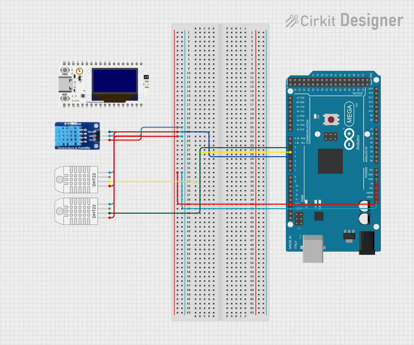
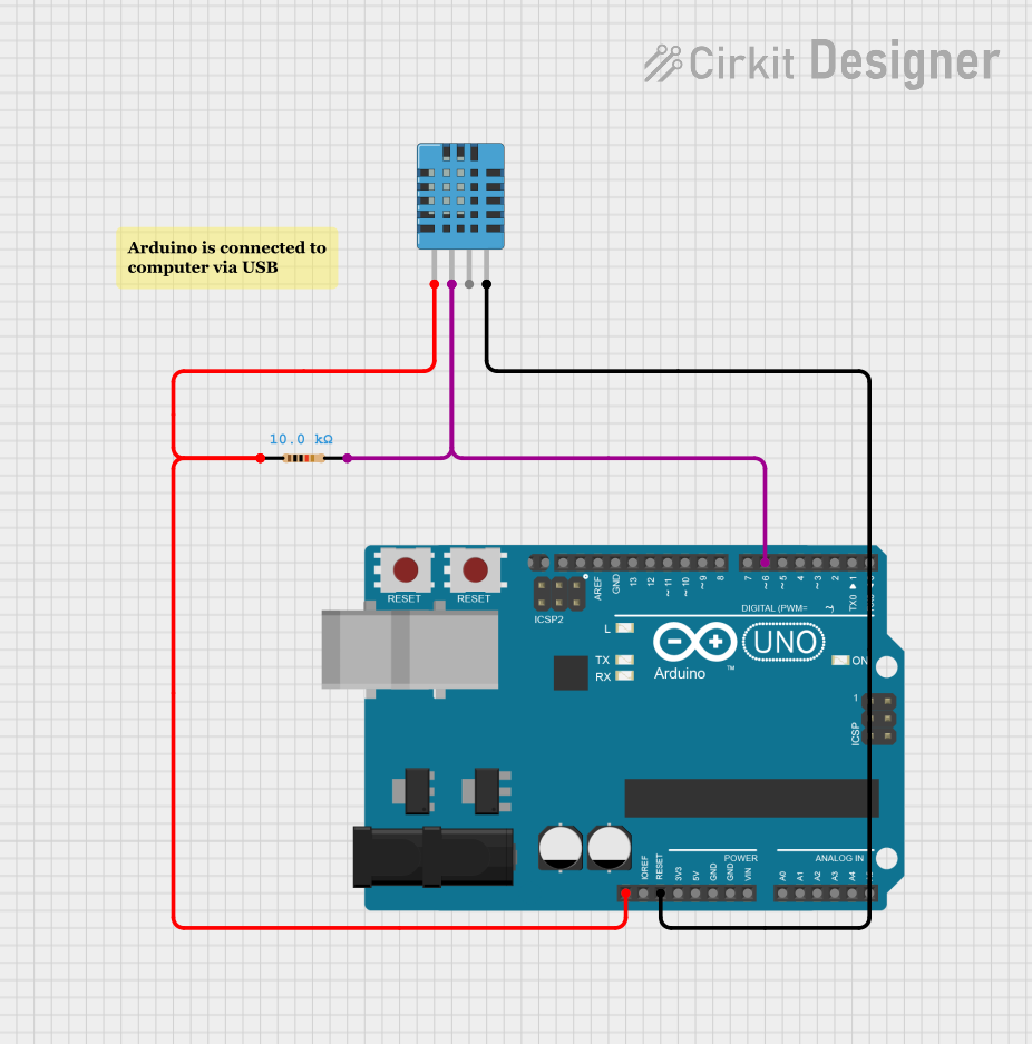
Connecting the DHT11 Sensor to a Circuit

  1. Connect the VCC pin to a 3.3V or 5V power supply.
  2. Connect the GND pin to the ground of the power supply.
  3. Connect the DATA pin to a digital input pin on your microcontroller.

Important Considerations and Best Practices

  • Ensure that the power supply is stable and within the specified voltage range.
  • Do not exceed the maximum sampling rate of 1Hz to prevent self-heating and inaccurate readings.
  • Use a pull-up resistor (typically 4.7kΩ to 10kΩ) between the DATA pin and VCC if the microcontroller does not have built-in pull-up resistors.
  • Avoid placing the sensor in direct sunlight or near heat sources to get accurate readings.
  • Allow the sensor to acclimate to the environment for accurate readings, especially if there are sudden changes in temperature or humidity.

Example Code for Arduino UNO

#include "DHT.h"

#define DHTPIN 2     // Digital pin connected to the DHT sensor
#define DHTTYPE DHT11 // DHT 11

DHT dht(DHTPIN, DHTTYPE);

void setup() {
  Serial.begin(9600);
  dht.begin();
}

void loop() {
  // Wait a few seconds between measurements.
  delay(2000);

  // Reading temperature or humidity takes about 250 milliseconds!
  float humidity = dht.readHumidity();
  // Read temperature as Celsius (the default)
  float temperature = dht.readTemperature();

  // Check if any reads failed and exit early (to try again).
  if (isnan(humidity) || isnan(temperature)) {
    Serial.println("Failed to read from DHT sensor!");
    return;
  }

  // Compute heat index in Celsius (isFahrenheit = false)
  float heatIndex = dht.computeHeatIndex(temperature, humidity, false);

  Serial.print("Humidity: ");
  Serial.print(humidity);
  Serial.print("%  Temperature: ");
  Serial.print(temperature);
  Serial.print("°C  Heat index: ");
  Serial.print(heatIndex);
  Serial.println("°C");
}

Troubleshooting and FAQs

Common Issues

  • Inaccurate Readings: Ensure the sensor is not placed near heat sources and is not exposed to direct sunlight.
  • No Data: Check the wiring, ensure the pull-up resistor is in place, and that the power supply is within the specified range.
  • Sensor Heating Up: Ensure the sampling rate does not exceed 1Hz.

Solutions and Tips for Troubleshooting

  • Wiring Issues: Double-check the connections and ensure that the DATA pin is connected to the correct digital pin on the microcontroller.
  • Pull-up Resistor: If the data line is unstable, add a pull-up resistor if not already in place.
  • Power Supply: Verify that the power supply is stable and within the 3.3V to 5V range.

FAQs

Q: Can I use the DHT11 sensor outdoors? A: Yes, but it should be protected from direct sunlight and water.

Q: How long does the DHT11 sensor last? A: With proper use, the DHT11 can last for several years.

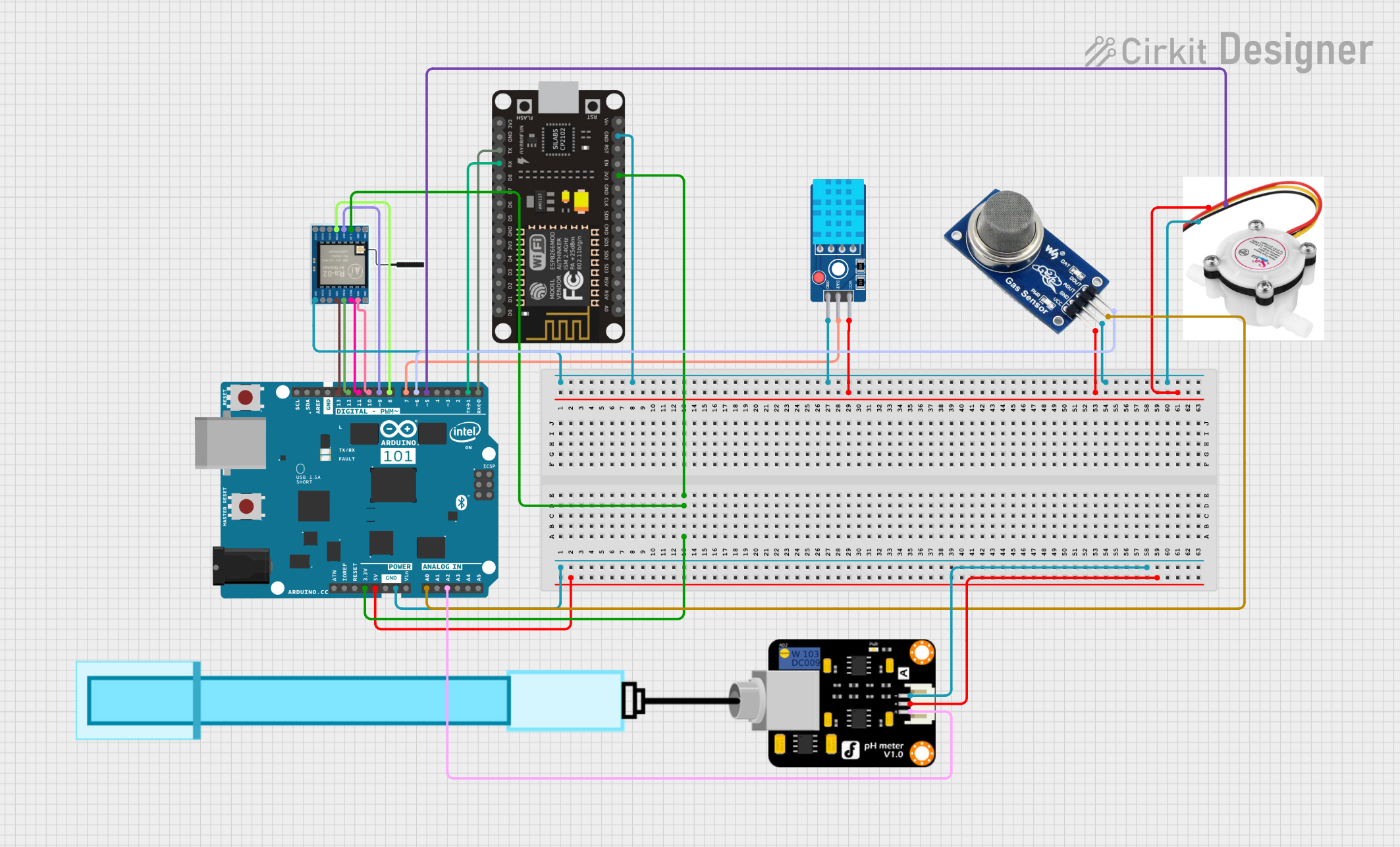
Q: Can I use multiple DHT11 sensors on the same microcontroller? A: Yes, each sensor will require a separate digital pin for the data signal.

Q: How do I calibrate the DHT11 sensor? A: The DHT11 is factory calibrated and does not typically require additional calibration. If precision is critical, consider using a more accurate sensor.

Q: What is the operating range of the DHT11 sensor? A: The DHT11 operates from 0 to 50°C for temperature and from 20% to 80% for humidity, with specified accuracy ranges.