
How to Use Basic FET N-Channel: Examples, Pinouts, and Specs
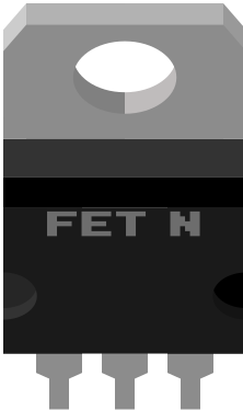
 Design with Basic FET N-Channel in Cirkit Designer
Introduction
The Basic FET N-Channel is a type of Field Effect Transistor (FET) that utilizes an N-type semiconductor to control current flow. It operates by applying a voltage to the gate terminal, which modulates the conductivity of the channel between the source and drain terminals. This component is widely used in electronic circuits for switching and amplification purposes due to its high efficiency and fast switching speeds.
Explore Projects Built with Basic FET N-Channel
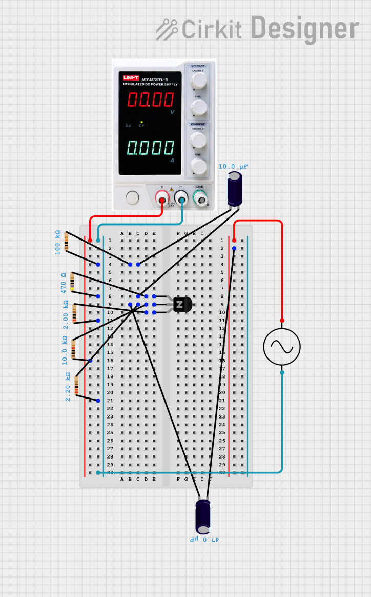 Open Project in Cirkit Designer
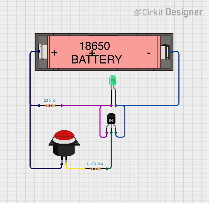 Open Project in Cirkit Designer
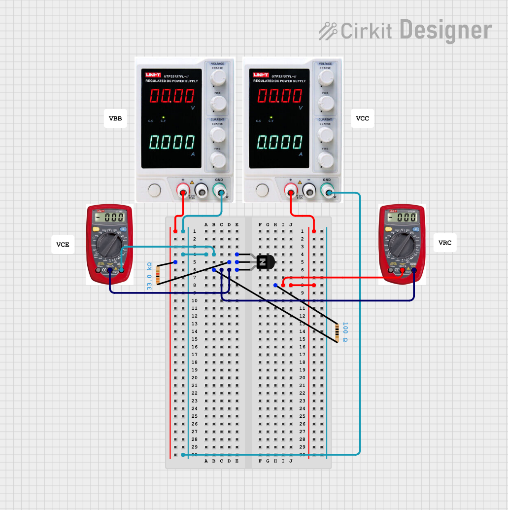 Open Project in Cirkit Designer
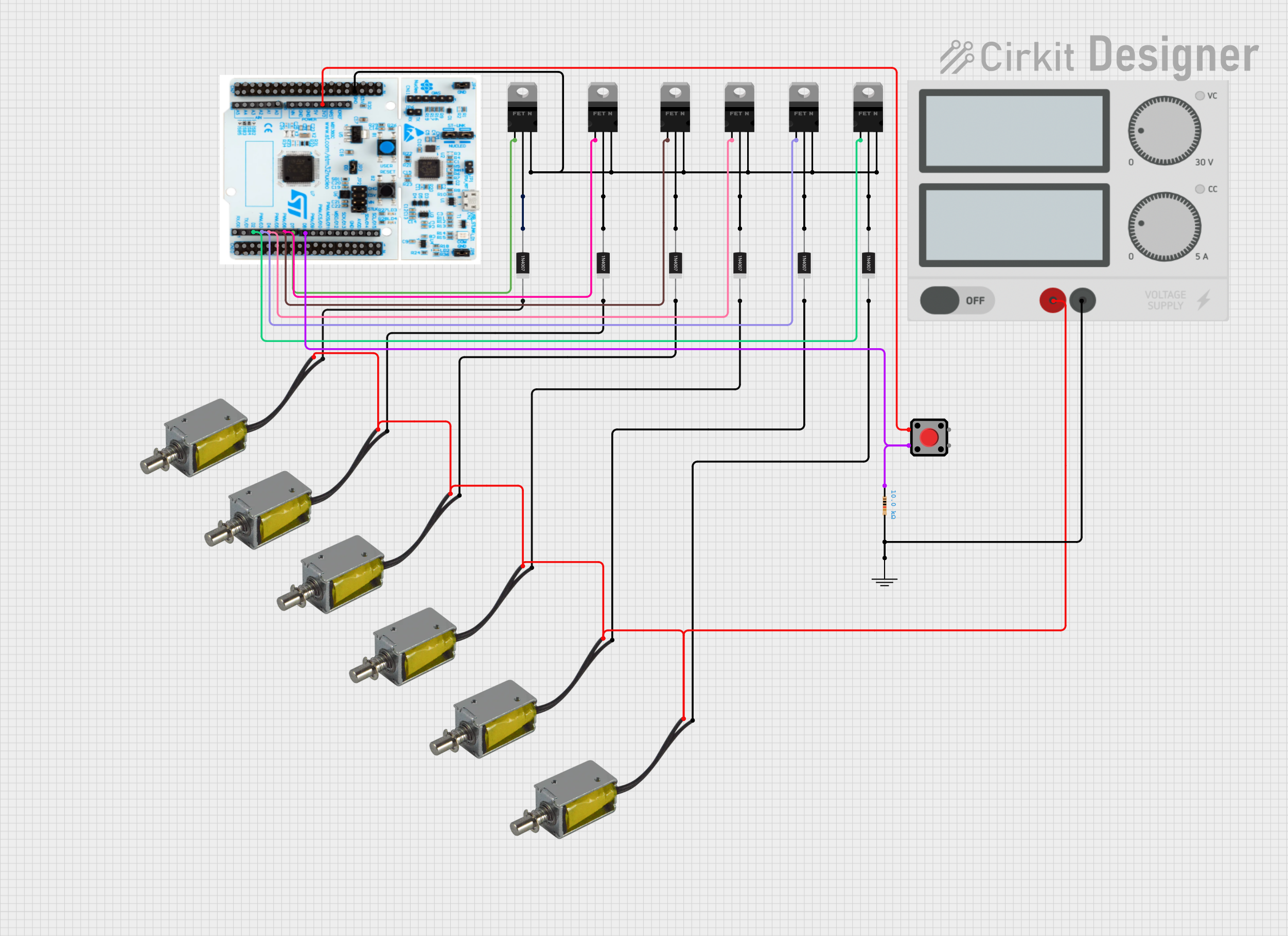 Open Project in Cirkit Designer
Explore Projects Built with Basic FET N-Channel
Open Project in Cirkit DesignerOpen Project in Cirkit DesignerOpen Project in Cirkit DesignerOpen Project in Cirkit DesignerCommon Applications and Use Cases
- Switching Applications: Used in power supplies, motor drivers, and LED drivers.
- Amplification: Commonly used in audio amplifiers and signal processing circuits.
- Digital Logic Circuits: Acts as a switch in microcontroller-based systems.
- Voltage Regulation: Used in DC-DC converters and voltage regulators.
Technical Specifications
Below are the key technical details for a typical Basic FET N-Channel:
| Parameter | Value |
|---|---|
| Maximum Drain-Source Voltage (VDS) | 60V |
| Maximum Gate-Source Voltage (VGS) | ±20V |
| Continuous Drain Current (ID) | 10A |
| Power Dissipation (PD) | 50W |
| RDS(on) (On-State Resistance) | 0.05Ω |
| Gate Threshold Voltage (VGS(th)) | 2V - 4V |
| Operating Temperature Range | -55°C to +150°C |
Pin Configuration and Descriptions
The Basic FET N-Channel typically has three pins:
| Pin | Name | Description |
|---|---|---|
| 1 | Gate (G) | Controls the flow of current between the drain and source by applying a voltage. |
| 2 | Drain (D) | The terminal through which current flows out of the FET. |
| 3 | Source (S) | The terminal through which current enters the FET. |
Usage Instructions
How to Use the Component in a Circuit
Basic Switching Circuit:
- Connect the source terminal to ground.
- Connect the drain terminal to the load (e.g., a motor or LED) and then to the positive supply voltage.
- Apply a voltage to the gate terminal to turn the FET on. Ensure the gate voltage exceeds the gate threshold voltage (VGS(th)) for proper operation.
Gate Resistor:
- Use a resistor (typically 10Ω to 1kΩ) between the gate and the control signal to limit inrush current and protect the gate.
Flyback Diode:
- When driving inductive loads (e.g., motors or relays), place a flyback diode across the load to protect the FET from voltage spikes.
Important Considerations and Best Practices
- Gate Voltage Levels: Ensure the gate voltage is within the specified range (typically 10V for full enhancement) to avoid damaging the FET.
- Heat Dissipation: Use a heatsink or proper thermal management if the FET operates at high currents to prevent overheating.
- Static Sensitivity: Handle the FET carefully to avoid damage from electrostatic discharge (ESD). Use anti-static precautions.
- RDS(on) Selection: Choose a FET with a low RDS(on) value for higher efficiency in switching applications.
Example: Using the Basic FET N-Channel with Arduino UNO
Below is an example of using the Basic FET N-Channel to control an LED with an Arduino UNO:
// Define the pin connected to the FET gate
const int fetGatePin = 9; // Pin 9 is used to control the FET

void setup() {
  pinMode(fetGatePin, OUTPUT); // Set the FET gate pin as an output
}

void loop() {
  digitalWrite(fetGatePin, HIGH); // Turn on the FET (LED ON)
  delay(1000);                    // Wait for 1 second
  digitalWrite(fetGatePin, LOW);  // Turn off the FET (LED OFF)
  delay(1000);                    // Wait for 1 second
}
Note: Ensure the gate resistor is connected between the Arduino pin and the FET gate to protect the microcontroller.
Troubleshooting and FAQs
Common Issues and Solutions
FET Not Turning On:
- Cause: Insufficient gate voltage.
- Solution: Verify that the gate voltage exceeds the gate threshold voltage (VGS(th)).
Excessive Heat:
- Cause: High current or inadequate heat dissipation.
- Solution: Use a heatsink or reduce the load current.
FET Always On or Off:
- Cause: Damaged FET due to ESD or overvoltage.
- Solution: Replace the FET and ensure proper handling and voltage limits.
Load Not Operating Properly:
- Cause: Incorrect wiring or insufficient power supply.
- Solution: Double-check the circuit connections and ensure the power supply meets the load requirements.
FAQs
Q1: Can I use the Basic FET N-Channel for AC applications?
A1: No, this FET is designed for DC applications. For AC, consider using a TRIAC or other suitable components.
Q2: What is the purpose of the gate resistor?
A2: The gate resistor limits the inrush current to the gate, protecting both the FET and the control circuit.
Q3: How do I calculate the required heatsink size?
A3: Use the formula:
[
R_{\text{th}} = \frac{T_{\text{max}} - T_{\text{ambient}}}{P_{\text{dissipation}}}
]
Where ( R_{\text{th}} ) is the thermal resistance of the heatsink, ( T_{\text{max}} ) is the maximum operating temperature, ( T_{\text{ambient}} ) is the ambient temperature, and ( P_{\text{dissipation}} ) is the power dissipated by the FET.
Q4: Can I drive the FET directly from a 3.3V microcontroller?
A4: It depends on the FET's gate threshold voltage. If the VGS(th) is low enough (e.g., logic-level FETs), it may work. Otherwise, use a gate driver circuit.