
How to Use Netduino Mini: Examples, Pinouts, and Specs
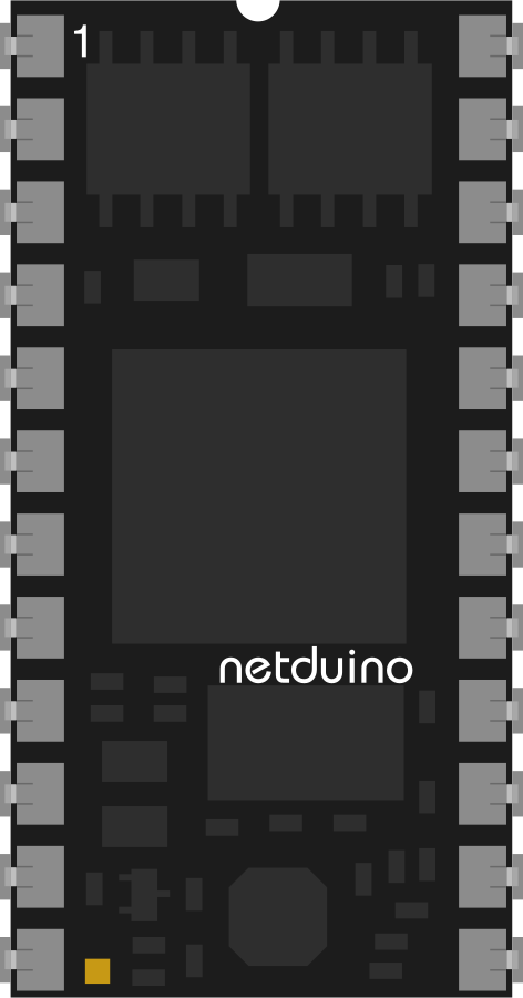
 Design with Netduino Mini in Cirkit Designer
Introduction
The Netduino Mini is a compact microcontroller board that combines the power of the .NET Micro Framework with the versatility of an Arduino-compatible platform. Designed for developers and hobbyists, it enables easy programming in C# and seamless integration with a wide range of sensors, actuators, and devices. Its small form factor makes it ideal for embedded systems, robotics, and IoT applications.
Explore Projects Built with Netduino Mini
 Open Project in Cirkit Designer
 Open Project in Cirkit Designer
 Open Project in Cirkit Designer
 Open Project in Cirkit Designer
Explore Projects Built with Netduino Mini
Open Project in Cirkit DesignerOpen Project in Cirkit DesignerOpen Project in Cirkit DesignerOpen Project in Cirkit DesignerCommon Applications and Use Cases
- Embedded systems and automation projects
- Internet of Things (IoT) devices
- Robotics and motor control
- Prototyping and educational projects
- Sensor data acquisition and processing
Technical Specifications
Key Technical Details
- Microcontroller: Atmel AT91SAM7X512 (ARM7, 32-bit)
- Clock Speed: 48 MHz
- Flash Memory: 512 KB
- RAM: 128 KB
- Input Voltage: 5V (regulated) or 7-12V (unregulated)
- Digital I/O Pins: 16 (3.3V logic level)
- PWM Channels: 4
- Analog Inputs: 4 (10-bit resolution)
- Communication Interfaces: UART, SPI, I2C
- Programming Interface: USB (via TTL serial adapter)
- Dimensions: 1.2" x 0.6" (30.5mm x 15.2mm)
Pin Configuration and Descriptions
The Netduino Mini has a 24-pin DIP layout. Below is the pin configuration:
| Pin | Name | Description |
|---|---|---|
| 1 | GND | Ground connection |
| 2 | VIN | Input voltage (7-12V unregulated) |
| 3 | 3.3V | Regulated 3.3V output |
| 4 | RESET | Reset pin (active low) |
| 5 | TX (UART) | UART Transmit (3.3V logic level) |
| 6 | RX (UART) | UART Receive (3.3V logic level) |
| 7-10 | D0-D3 | Digital I/O pins (3.3V logic level) |
| 11-14 | PWM0-PWM3 | PWM output pins |
| 15-18 | A0-A3 | Analog input pins (10-bit resolution) |
| 19 | SCL (I2C) | I2C Clock line |
| 20 | SDA (I2C) | I2C Data line |
| 21 | SPI_MOSI | SPI Master Out Slave In |
| 22 | SPI_MISO | SPI Master In Slave Out |
| 23 | SPI_SCK | SPI Clock |
| 24 | SPI_SS | SPI Slave Select |
Usage Instructions
How to Use the Netduino Mini in a Circuit
Powering the Board:
- Connect a regulated 5V supply to the
3.3Vpin or an unregulated 7-12V supply to theVINpin. - Ensure proper grounding by connecting the
GNDpin to the ground of your circuit.
- Connect a regulated 5V supply to the
Programming the Board:
- Use a USB-to-TTL serial adapter to connect the
TXandRXpins to your computer. - Install the .NET Micro Framework SDK and the Netduino SDK on your computer.
- Write your program in C# using Visual Studio or Visual Studio Code.
- Deploy the program to the Netduino Mini via the USB-to-TTL adapter.
- Use a USB-to-TTL serial adapter to connect the
Connecting Sensors and Actuators:
- Use the digital I/O pins (
D0-D3) for controlling LEDs, relays, or other digital devices. - Connect analog sensors to the analog input pins (
A0-A3) for reading sensor data. - Use the PWM pins (
PWM0-PWM3) for motor control or dimming LEDs.
- Use the digital I/O pins (
Important Considerations and Best Practices
- Voltage Levels: The Netduino Mini operates at 3.3V logic levels. Ensure that any connected devices are compatible or use level shifters.
- Power Supply: Avoid exceeding the recommended input voltage range to prevent damage to the board.
- Pin Current Limits: Do not exceed 8mA per I/O pin to avoid damaging the microcontroller.
- Debugging: Use the built-in debugging features of the .NET Micro Framework for efficient troubleshooting.
Example: Blinking an LED with Netduino Mini
Below is an example of how to blink an LED connected to pin D0:
using System;
using Microsoft.SPOT;
using Microsoft.SPOT.Hardware;

namespace NetduinoMiniExample
{
    public class Program
    {
        public static void Main()
        {
            // Initialize digital output pin D0
            OutputPort led = new OutputPort(Cpu.Pin.GPIO_Pin0, false);

            while (true)
            {
                led.Write(true);  // Turn LED on
                Thread.Sleep(500); // Wait for 500ms

                led.Write(false); // Turn LED off
                Thread.Sleep(500); // Wait for 500ms
            }
        }
    }
}
Troubleshooting and FAQs
Common Issues and Solutions
The board is not responding to programming commands.
- Ensure the USB-to-TTL adapter is properly connected to the
TXandRXpins. - Verify that the correct COM port is selected in your development environment.
- Check that the board is powered correctly.
- Ensure the USB-to-TTL adapter is properly connected to the
Connected devices are not functioning as expected.
- Confirm that the devices are compatible with 3.3V logic levels.
- Double-check wiring and connections for errors.
The board overheats or shuts down.
- Ensure the input voltage does not exceed 12V.
- Avoid drawing excessive current from the I/O pins.
FAQs
Q: Can I use the Netduino Mini with Arduino libraries?
A: No, the Netduino Mini uses the .NET Micro Framework and is programmed in C#. However, it is compatible with many Arduino shields and sensors.
Q: How do I reset the board?
A: Use the RESET pin to perform a hardware reset. Connect it to ground momentarily to reset the board.
Q: Can I use the Netduino Mini for IoT projects?
A: Yes, the Netduino Mini supports communication protocols like UART, SPI, and I2C, making it suitable for IoT applications.