Cirkit Designer Logo
Cirkit Designer
Your all-in-one circuit design IDE
Home / 
Component Documentation

How to Use motor driver: Examples, Pinouts, and Specs

Image of motor driver
Cirkit Designer LogoDesign with motor driver in Cirkit Designer

Introduction

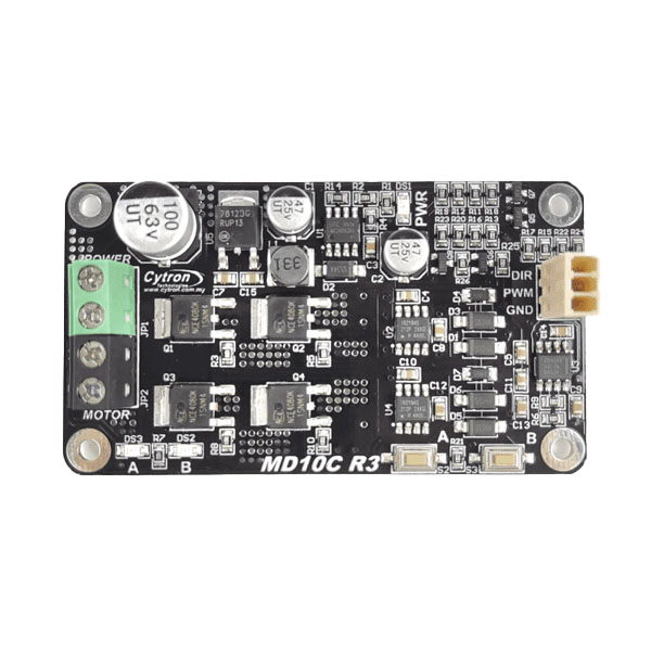
The Cytron MD10C is a robust and versatile motor driver designed to control DC motors with high efficiency and precision. It acts as an interface between a microcontroller (e.g., Arduino, Raspberry Pi) and a DC motor, enabling users to regulate the motor's speed and direction. The MD10C is particularly well-suited for applications requiring high current and voltage handling, such as robotics, automation systems, and motorized vehicles.

Explore Projects Built with motor driver

Use Cirkit Designer to design, explore, and prototype these projects online. Some projects support real-time simulation. Click "Open Project" to start designing instantly!
ESP32 and L298N Motor Driver Controlled Battery-Powered Robotic Car
Image of ESP 32 BT BOT: A project utilizing motor driver in a practical application
This circuit is a motor control system powered by a 12V battery, utilizing an L298N motor driver to control four DC gearmotors. An ESP32 microcontroller is used to send control signals to the motor driver, enabling precise control of the motors for applications such as a robotic vehicle.
Cirkit Designer LogoOpen Project in Cirkit Designer
ESP32-Controlled Dual Motor Driver with Optical Encoder Feedback
Image of Copy of Mobile Robot System with Speed and Position Control Using ESP32: A project utilizing motor driver in a practical application
This circuit is designed to control two DC motors using an L298N Dual Motor Driver Module, which receives PWM control signals from an ESP32 microcontroller. The motors' rotational movement can be monitored by two Optical Encoder Sensor Modules connected to the ESP32. Power is supplied by a 4 x AAA battery mount, with the battery's positive terminal connected to the motor driver's 12V input and the negative terminal to the common ground.
Cirkit Designer LogoOpen Project in Cirkit Designer
ESP32-Controlled Dual Motor Driver with Optical Encoder Feedback
Image of Mobile Robot System with Speed and Position Control Using ESP32: A project utilizing motor driver in a practical application
This circuit is designed to control two DC motors using an L298N Dual Motor Driver Module, which receives PWM control signals from an ESP32 microcontroller. The motors' rotational movement can be monitored by two Optical Encoder Sensor Modules, which are also interfaced with the ESP32. Power is supplied by a 4 x AAA battery mount, with the 12V line powering the motor driver and the 5V line stepping down to power the ESP32 and the encoder sensors.
Cirkit Designer LogoOpen Project in Cirkit Designer
ESP32-Controlled Dual Motor Driver for Robotic Vehicle
Image of ESP 32 BT BOT: A project utilizing motor driver in a practical application
This circuit is designed to control four DC gearmotors using an L298N motor driver module, which is interfaced with an ESP32 microcontroller. The ESP32 uses its GPIO pins to send control signals to the L298N driver, enabling the independent operation of the motors, such as direction and speed control. Power is supplied by a 12V battery connected to the motor driver, with the ESP32 receiving its power through a voltage regulator on the L298N module.
Cirkit Designer LogoOpen Project in Cirkit Designer

Explore Projects Built with motor driver

Use Cirkit Designer to design, explore, and prototype these projects online. Some projects support real-time simulation. Click "Open Project" to start designing instantly!
Image of ESP 32 BT BOT: A project utilizing motor driver in a practical application
ESP32 and L298N Motor Driver Controlled Battery-Powered Robotic Car
This circuit is a motor control system powered by a 12V battery, utilizing an L298N motor driver to control four DC gearmotors. An ESP32 microcontroller is used to send control signals to the motor driver, enabling precise control of the motors for applications such as a robotic vehicle.
Cirkit Designer LogoOpen Project in Cirkit Designer
Image of Copy of Mobile Robot System with Speed and Position Control Using ESP32: A project utilizing motor driver in a practical application
ESP32-Controlled Dual Motor Driver with Optical Encoder Feedback
This circuit is designed to control two DC motors using an L298N Dual Motor Driver Module, which receives PWM control signals from an ESP32 microcontroller. The motors' rotational movement can be monitored by two Optical Encoder Sensor Modules connected to the ESP32. Power is supplied by a 4 x AAA battery mount, with the battery's positive terminal connected to the motor driver's 12V input and the negative terminal to the common ground.
Cirkit Designer LogoOpen Project in Cirkit Designer
Image of Mobile Robot System with Speed and Position Control Using ESP32: A project utilizing motor driver in a practical application
ESP32-Controlled Dual Motor Driver with Optical Encoder Feedback
This circuit is designed to control two DC motors using an L298N Dual Motor Driver Module, which receives PWM control signals from an ESP32 microcontroller. The motors' rotational movement can be monitored by two Optical Encoder Sensor Modules, which are also interfaced with the ESP32. Power is supplied by a 4 x AAA battery mount, with the 12V line powering the motor driver and the 5V line stepping down to power the ESP32 and the encoder sensors.
Cirkit Designer LogoOpen Project in Cirkit Designer
Image of ESP 32 BT BOT: A project utilizing motor driver in a practical application
ESP32-Controlled Dual Motor Driver for Robotic Vehicle
This circuit is designed to control four DC gearmotors using an L298N motor driver module, which is interfaced with an ESP32 microcontroller. The ESP32 uses its GPIO pins to send control signals to the L298N driver, enabling the independent operation of the motors, such as direction and speed control. Power is supplied by a 12V battery connected to the motor driver, with the ESP32 receiving its power through a voltage regulator on the L298N module.
Cirkit Designer LogoOpen Project in Cirkit Designer

Common Applications

  • Robotics and automation systems
  • Electric vehicles and motorized carts
  • Conveyor belts and industrial machinery
  • DIY projects involving DC motor control

Technical Specifications

The Cytron MD10C motor driver is designed to handle a wide range of DC motor control requirements. Below are its key technical specifications:

Parameter Specification
Operating Voltage 7V to 30V DC
Continuous Current Up to 10A
Peak Current 30A (for 10 seconds)
Control Signal Voltage 3.3V or 5V logic compatible
PWM Frequency Up to 20 kHz
Motor Direction Control Forward and Reverse
Protection Features Overcurrent, Overtemperature, and Reverse Polarity

Pin Configuration and Descriptions

The MD10C features a simple pinout for easy integration into your circuit. Below is the pin configuration:

Pin Name Type Description
VM Power Input Connect to the positive terminal of the motor power supply (7V to 30V).
GND Power Ground Connect to the ground of the motor power supply and the microcontroller.
PWM Input Signal Pulse Width Modulation (PWM) input for speed control (3.3V or 5V logic).
DIR Input Signal Direction control input: HIGH for forward, LOW for reverse (3.3V or 5V logic).
MOTOR+ Motor Output Connect to the positive terminal of the DC motor.
MOTOR- Motor Output Connect to the negative terminal of the DC motor.

Usage Instructions

How to Use the MD10C in a Circuit

  1. Power Supply: Connect the VM pin to a DC power supply (7V to 30V) and the GND pin to the ground of the power supply.
  2. Motor Connection: Connect the MOTOR+ and MOTOR- pins to the terminals of the DC motor.
  3. Control Signals:
    • Connect the PWM pin to a PWM-capable pin on your microcontroller for speed control.
    • Connect the DIR pin to a digital output pin on your microcontroller for direction control.
  4. Logic Voltage Compatibility: Ensure the control signals (PWM and DIR) are compatible with 3.3V or 5V logic levels.

Important Considerations

  • Heat Dissipation: The MD10C can handle high currents, so ensure proper ventilation or use a heatsink if operating near the maximum current rating.
  • Power Supply: Use a power supply capable of providing sufficient current for your motor to avoid voltage drops.
  • PWM Frequency: For optimal performance, use a PWM frequency between 10 kHz and 20 kHz.

Example: Using MD10C with Arduino UNO

Below is an example Arduino sketch to control a DC motor using the MD10C:

// Define pin connections
const int pwmPin = 9;  // PWM pin connected to MD10C's PWM input
const int dirPin = 8;  // Direction pin connected to MD10C's DIR input

void setup() {
  // Set pin modes
  pinMode(pwmPin, OUTPUT);
  pinMode(dirPin, OUTPUT);
}

void loop() {
  // Rotate motor forward at 50% speed
  digitalWrite(dirPin, HIGH);  // Set direction to forward
  analogWrite(pwmPin, 128);    // Set speed (128/255 = 50%)
  delay(3000);                 // Run for 3 seconds

  // Rotate motor in reverse at 75% speed
  digitalWrite(dirPin, LOW);   // Set direction to reverse
  analogWrite(pwmPin, 192);    // Set speed (192/255 = 75%)
  delay(3000);                 // Run for 3 seconds
}

Best Practices

  • Always double-check your wiring before powering the circuit to avoid damage to the motor driver or other components.
  • Use a fuse or circuit breaker to protect the motor driver and motor from overcurrent conditions.
  • Avoid sudden changes in direction at high speeds to prevent mechanical stress on the motor.

Troubleshooting and FAQs

Common Issues and Solutions

  1. Motor Not Running

    • Cause: Incorrect wiring or insufficient power supply.
    • Solution: Verify all connections and ensure the power supply meets the voltage and current requirements.
  2. Motor Running in the Wrong Direction

    • Cause: DIR pin logic level is incorrect.
    • Solution: Check the DIR pin signal and ensure it matches the desired direction.
  3. Motor Speed Not Changing

    • Cause: PWM signal not being generated or incorrect frequency.
    • Solution: Verify the PWM signal from the microcontroller using an oscilloscope or multimeter.
  4. Overheating

    • Cause: Prolonged operation at high current without proper cooling.
    • Solution: Add a heatsink or improve ventilation around the motor driver.

FAQs

  • Q: Can I use the MD10C with a 3.3V microcontroller?
    A: Yes, the MD10C is compatible with both 3.3V and 5V logic levels.

  • Q: What is the maximum motor voltage I can use?
    A: The MD10C supports motor voltages between 7V and 30V.

  • Q: Can I control two motors with one MD10C?
    A: No, the MD10C is designed to control a single DC motor.

  • Q: Is the MD10C suitable for stepper motors?
    A: No, the MD10C is specifically designed for DC motors, not stepper motors.

By following this documentation, you can effectively integrate the Cytron MD10C motor driver into your projects for precise and reliable motor control.