
Cirkit Designer
Your all-in-one circuit design IDE
Home /
Component Documentation
How to Use thermocouple: Examples, Pinouts, and Specs
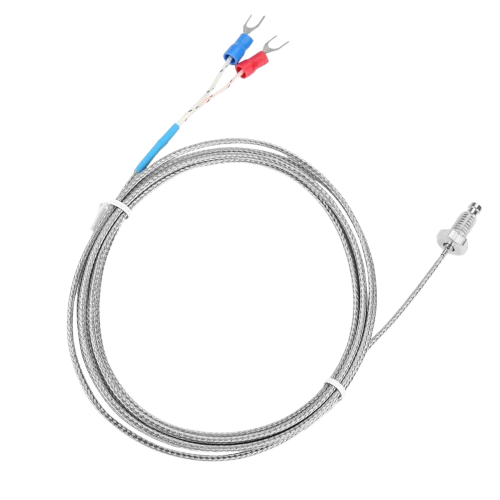
 Design with thermocouple in Cirkit Designer
Introduction
- A thermocouple is a temperature sensor that consists of two dissimilar metal wires joined at one end. It generates a voltage proportional to the temperature difference between the joined end (hot junction) and the other ends (cold junction or reference junction) of the wires. This voltage can be measured and converted into a temperature reading.
- Thermocouples are widely used in industrial, scientific, and household applications due to their wide temperature range, durability, and fast response time. Common applications include temperature monitoring in furnaces, engines, HVAC systems, and food processing.
Explore Projects Built with thermocouple
PID Temperature Control System with Thermocouple and SSR
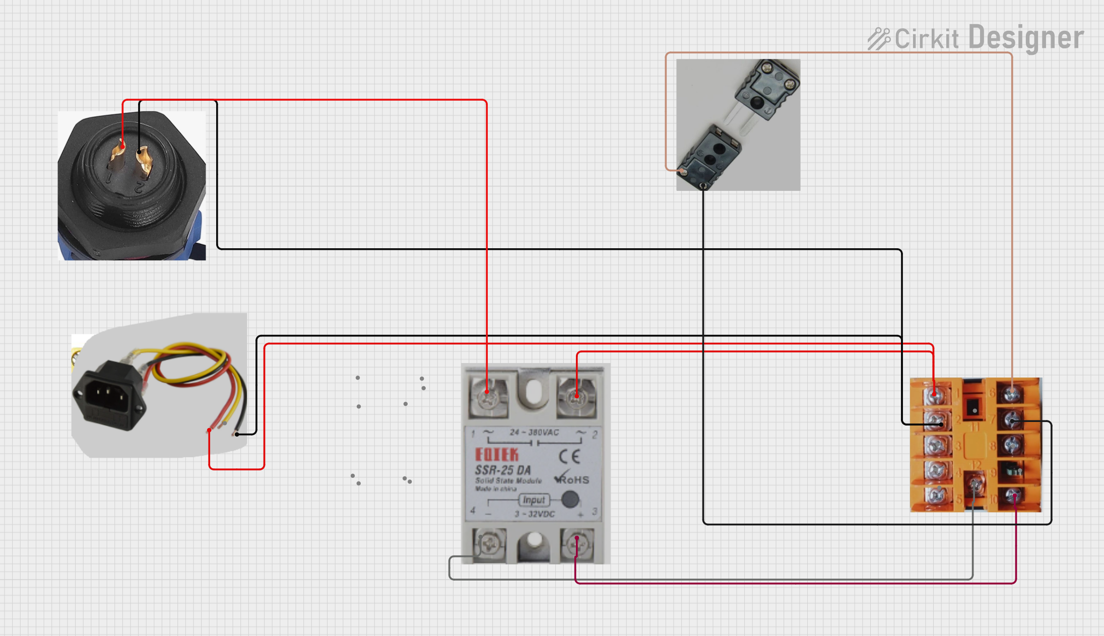
This circuit is a temperature control system that uses a thermocouple to measure temperature and a PID controller to regulate it. The PID controller drives a solid-state relay (SSR) to control an external load, with power supplied through an AC inlet socket.
Open Project in Cirkit DesignerArduino UNO Based Temperature Monitoring System with OLED Display
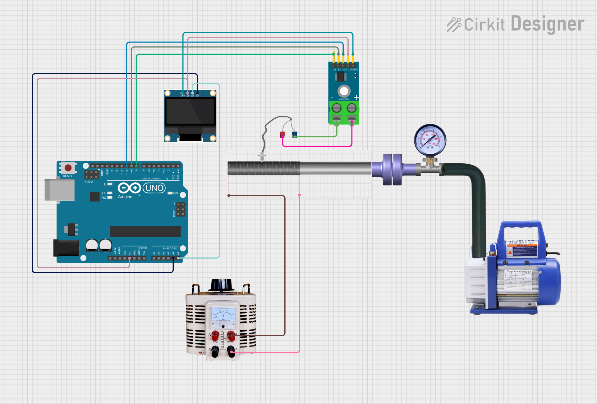
This circuit features an Arduino UNO microcontroller interfaced with a MAX6675 thermocouple module and a 0.96" OLED display. The Arduino reads temperature data from the MAX6675 module, which is connected to a K-type thermocouple, and communicates with the OLED display via I2C to show the temperature readings. Additionally, there are unused components such as a flange, rotary pump, pressure gauge, hose, and a variable transformer connected to a quartz crystal, which do not seem to be integrated into the main functionality of the circuit based on the provided net list and code.
Open Project in Cirkit DesignerArduino UNO Thermocouple Temperature Monitor with I2C LCD Display
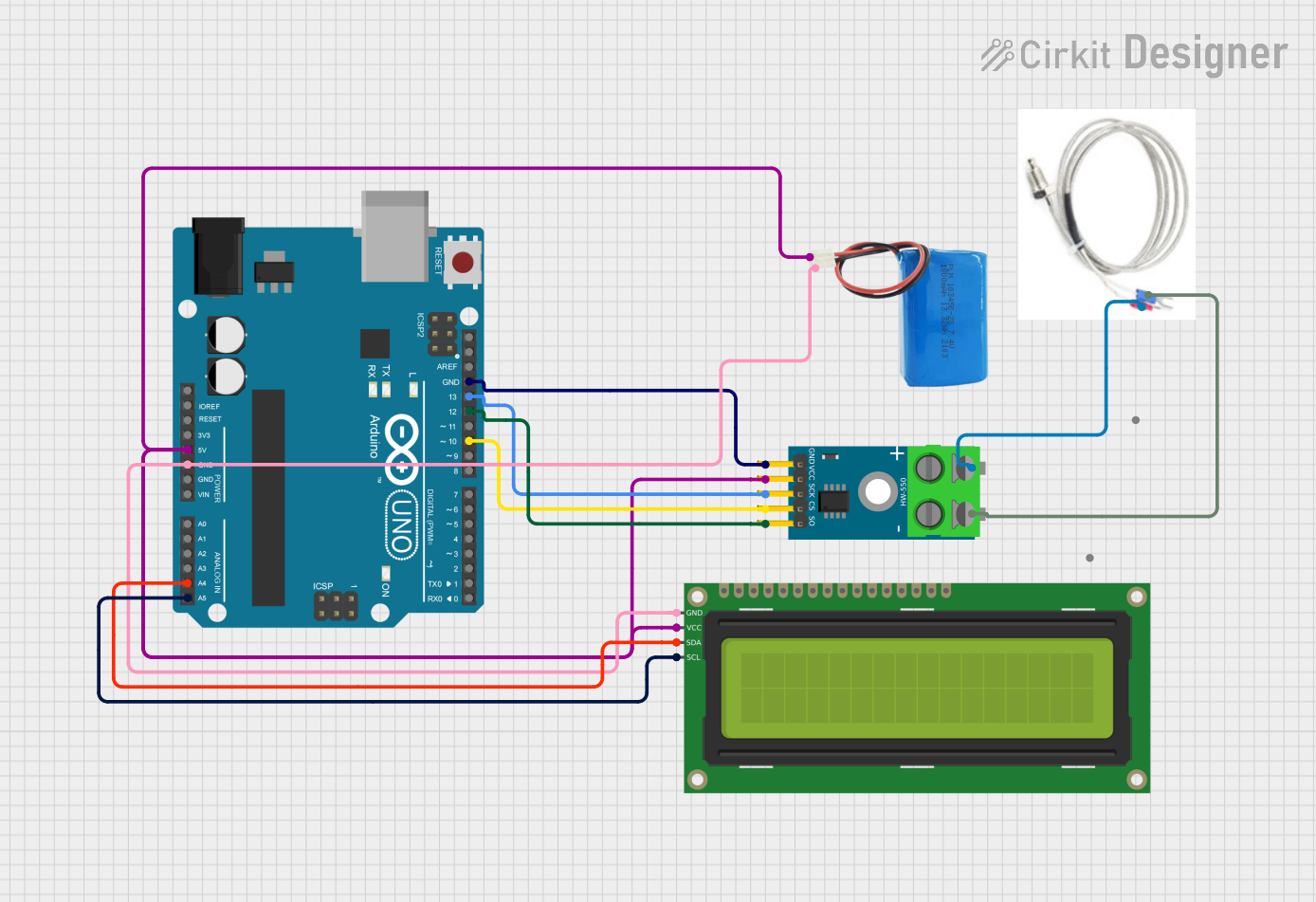
This circuit is a temperature measurement system using an Arduino UNO, a MAX6675 thermocouple module, and a 16x2 I2C LCD. The Arduino reads temperature data from the thermocouple via the MAX6675 module and displays the temperature in both Celsius and Fahrenheit on the LCD.
Open Project in Cirkit DesignerArduino Mega 2560 and MAX6675 Thermocouple Temperature Sensor
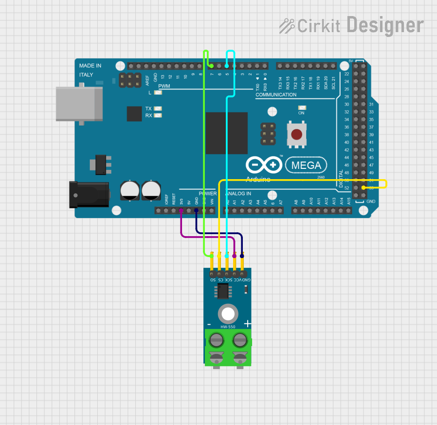
This circuit consists of an Arduino Mega 2560 microcontroller connected to a MAX6675 thermocouple temperature sensor module. The Arduino provides power to the MAX6675 module and reads temperature data via digital pins, enabling temperature monitoring and data acquisition.
Open Project in Cirkit DesignerExplore Projects Built with thermocouple
PID Temperature Control System with Thermocouple and SSR
This circuit is a temperature control system that uses a thermocouple to measure temperature and a PID controller to regulate it. The PID controller drives a solid-state relay (SSR) to control an external load, with power supplied through an AC inlet socket.
Open Project in Cirkit DesignerArduino UNO Based Temperature Monitoring System with OLED Display
This circuit features an Arduino UNO microcontroller interfaced with a MAX6675 thermocouple module and a 0.96" OLED display. The Arduino reads temperature data from the MAX6675 module, which is connected to a K-type thermocouple, and communicates with the OLED display via I2C to show the temperature readings. Additionally, there are unused components such as a flange, rotary pump, pressure gauge, hose, and a variable transformer connected to a quartz crystal, which do not seem to be integrated into the main functionality of the circuit based on the provided net list and code.
Open Project in Cirkit DesignerArduino UNO Thermocouple Temperature Monitor with I2C LCD Display
This circuit is a temperature measurement system using an Arduino UNO, a MAX6675 thermocouple module, and a 16x2 I2C LCD. The Arduino reads temperature data from the thermocouple via the MAX6675 module and displays the temperature in both Celsius and Fahrenheit on the LCD.
Open Project in Cirkit DesignerArduino Mega 2560 and MAX6675 Thermocouple Temperature Sensor
This circuit consists of an Arduino Mega 2560 microcontroller connected to a MAX6675 thermocouple temperature sensor module. The Arduino provides power to the MAX6675 module and reads temperature data via digital pins, enabling temperature monitoring and data acquisition.
Open Project in Cirkit DesignerTechnical Specifications
- Temperature Range: Varies by thermocouple type (e.g., Type K: -200°C to 1350°C)
- Accuracy: Typically ±1°C to ±2°C, depending on the type and calibration
- Output Voltage: Microvolts per degree Celsius (varies by type)
- Response Time: Milliseconds to seconds, depending on the design
- Material: Depends on the thermocouple type (e.g., Type K uses Chromel and Alumel)
Common Thermocouple Types and Characteristics
| Type | Material Combination | Temperature Range | Sensitivity (µV/°C) |
|---|---|---|---|
| K | Chromel-Alumel | -200°C to 1350°C | ~41 |
| J | Iron-Constantan | -40°C to 750°C | ~55 |
| T | Copper-Constantan | -200°C to 350°C | ~43 |
| E | Chromel-Constantan | -200°C to 900°C | ~68 |
| N | Nicrosil-Nisil | -200°C to 1300°C | ~39 |
Pin Configuration and Descriptions
Thermocouples do not have a standard "pinout" like integrated circuits. Instead, they consist of two wires:
| Wire Color (IEC Standard) | Material | Description |
|---|---|---|
| Positive (e.g., Green) | Chromel, Iron, etc. | Connected to the positive terminal of the measurement device |
| Negative (e.g., White) | Alumel, Constantan, etc. | Connected to the negative terminal of the measurement device |
Note: Wire colors may vary by region or standard (e.g., ANSI, IEC).
Usage Instructions
Connecting the Thermocouple:
- Connect the positive wire to the positive input of the measurement device (e.g., a thermocouple amplifier or microcontroller ADC).
- Connect the negative wire to the negative input of the measurement device.
- Use a thermocouple amplifier (e.g., MAX31855 or MAX6675) to amplify and linearize the thermocouple's small voltage output.
Using with an Arduino UNO:
- To interface a thermocouple with an Arduino UNO, use a thermocouple amplifier module (e.g., MAX6675).
- Connect the amplifier module to the Arduino as follows:
- VCC: Connect to Arduino 5V
- GND: Connect to Arduino GND
- DO (Data Out): Connect to Arduino digital pin (e.g., D4)
- CS (Chip Select): Connect to Arduino digital pin (e.g., D5)
- CLK (Clock): Connect to Arduino digital pin (e.g., D6)
Arduino Code Example:
#include <SPI.h>
#include "Adafruit_MAX31855.h"

// Define pins for the MAX31855 module
#define DO_PIN 4  // Data Out pin
#define CS_PIN 5  // Chip Select pin
#define CLK_PIN 6 // Clock pin

// Create an instance of the MAX31855 library
Adafruit_MAX31855 thermocouple(CLK_PIN, CS_PIN, DO_PIN);

void setup() {
  Serial.begin(9600);
  Serial.println("Thermocouple Test");

  // Check if the thermocouple is connected properly
  if (!thermocouple.begin()) {
    Serial.println("Error: Thermocouple not detected. Check connections.");
    while (1); // Halt execution if no thermocouple is detected
  }
}

void loop() {
  // Read the temperature in Celsius
  double temperature = thermocouple.readCelsius();

  // Check for errors
  if (isnan(temperature)) {
    Serial.println("Error: Failed to read temperature.");
  } else {
    Serial.print("Temperature: ");
    Serial.print(temperature);
    Serial.println(" °C");
  }

  delay(1000); // Wait 1 second before the next reading
}
- Important Considerations:
- Ensure proper cold-junction compensation for accurate readings.
- Avoid sharp bends or excessive mechanical stress on the thermocouple wires.
- Use shielded cables or twisted pairs to minimize electrical noise in long wire runs.
- Match the thermocouple type to the amplifier or measurement device.
Troubleshooting and FAQs
Common Issues
Inaccurate Temperature Readings:
- Cause: Poor cold-junction compensation or incorrect thermocouple type selected.
- Solution: Verify the amplifier/module settings and ensure proper cold-junction compensation.
No Output or Erratic Readings:
- Cause: Loose or incorrect connections.
- Solution: Check all wiring and ensure the thermocouple is securely connected.
High Noise in Readings:
- Cause: Electrical interference or long wire runs.
- Solution: Use shielded cables, twisted pairs, or a low-pass filter to reduce noise.
Thermocouple Not Detected:
- Cause: Faulty thermocouple or amplifier module.
- Solution: Test with a known working thermocouple or replace the amplifier module.
FAQs
Can I extend thermocouple wires?
- Yes, but use thermocouple extension wires of the same material to avoid introducing errors.
What is cold-junction compensation?
- It is the process of accounting for the temperature at the reference junction to ensure accurate readings.
Can I use a thermocouple without an amplifier?
- Directly connecting a thermocouple to a microcontroller is not recommended due to its low voltage output. Use an amplifier for accurate measurements.
How do I choose the right thermocouple type?
- Select a type based on the required temperature range, sensitivity, and environmental conditions. For general-purpose use, Type K is a common choice.