How to Use SCD41: Examples, Pinouts, and Specs
Introduction
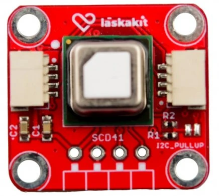
The SCD41 is a compact digital sensor manufactured by Laskakit for measuring carbon dioxide (CO2), temperature, and humidity. It employs non-dispersive infrared (NDIR) technology for accurate CO2 detection, making it ideal for applications requiring precise indoor air quality monitoring. The SCD41 is designed for ease of integration into various systems, offering a small form factor and digital I2C interface.
Explore Projects Built with SCD41


Explore Projects Built with SCD41
Common Applications
- Indoor air quality monitoring
- HVAC (Heating, Ventilation, and Air Conditioning) systems
- Smart home devices
- Air purifiers and ventilation systems
- Greenhouse monitoring
Technical Specifications
The following table outlines the key technical details of the SCD41 sensor:
| Parameter | Value |
|---|---|
| CO2 Measurement Range | 400 ppm to 5000 ppm |
| CO2 Accuracy | ±(40 ppm + 5% of reading) |
| Temperature Range | -10°C to 60°C |
| Temperature Accuracy | ±0.8°C |
| Humidity Range | 0% to 100% RH (non-condensing) |
| Humidity Accuracy | ±5% RH |
| Supply Voltage | 2.4 V to 5.5 V |
| Current Consumption | 2 mA (average), 5 mA (peak during measurement) |
| Communication Interface | I2C (7-bit address: 0x62) |
| Dimensions | 10.1 mm x 10.1 mm x 6.5 mm |
Pin Configuration and Descriptions
The SCD41 sensor has the following pinout:
| Pin | Name | Description |
|---|---|---|
| 1 | VDD | Power supply (2.4 V to 5.5 V) |
| 2 | GND | Ground |
| 3 | SDA | I2C data line |
| 4 | SCL | I2C clock line |
| 5 | SEL | Address select (connect to GND for default 0x62) |
| 6 | NC | Not connected (leave floating) |
Usage Instructions
How to Use the SCD41 in a Circuit
- Power Supply: Connect the VDD pin to a 3.3 V or 5 V power source and the GND pin to ground.
- I2C Communication: Connect the SDA and SCL pins to the corresponding I2C pins on your microcontroller. Use pull-up resistors (typically 4.7 kΩ) on the SDA and SCL lines if not already present.
- Address Selection: By default, the I2C address is 0x62. If you need to change the address, use the SEL pin as specified in the datasheet.
- Measurement: The sensor provides CO2, temperature, and humidity readings via I2C. Ensure proper initialization and periodic polling for data.
Important Considerations and Best Practices
- Warm-Up Time: Allow the sensor to warm up for at least 5 minutes after power-up for accurate readings.
- Ventilation: Ensure proper airflow around the sensor for reliable CO2 measurements.
- Humidity and Temperature: Avoid condensation on the sensor, as it may affect accuracy.
- I2C Pull-Up Resistors: Verify that pull-up resistors are present on the I2C lines to ensure proper communication.
- Calibration: The SCD41 is factory-calibrated, but periodic recalibration may be necessary for long-term accuracy.
Example Code for Arduino UNO
Below is an example of how to interface the SCD41 with an Arduino UNO using the I2C protocol:
#include <Wire.h>
#include <SensirionI2CScd4x.h> // Include the SCD41 library

SensirionI2CScd4x scd4x; // Create an instance of the SCD41 class

void setup() {
  Wire.begin(); // Initialize I2C communication
  Serial.begin(9600); // Start serial communication for debugging

  scd4x.begin(Wire); // Initialize the SCD41 sensor
  uint16_t error;
  char errorMessage[256];

  // Start periodic measurement
  error = scd4x.startPeriodicMeasurement();
  if (error) {
    scd4x.getErrorMessage(error, errorMessage, sizeof(errorMessage));
    Serial.print("Error starting measurement: ");
    Serial.println(errorMessage);
  } else {
    Serial.println("SCD41 measurement started successfully.");
  }
}

void loop() {
  uint16_t co2;
  float temperature;
  float humidity;
  uint16_t error;
  char errorMessage[256];

  // Wait for measurement data to be ready
  delay(5000); // SCD41 provides new data every 5 seconds

  // Read measurement data
  error = scd4x.readMeasurement(co2, temperature, humidity);
  if (error) {
    scd4x.getErrorMessage(error, errorMessage, sizeof(errorMessage));
    Serial.print("Error reading measurement: ");
    Serial.println(errorMessage);
  } else {
    Serial.print("CO2: ");
    Serial.print(co2);
    Serial.print(" ppm, Temperature: ");
    Serial.print(temperature);
    Serial.print(" °C, Humidity: ");
    Serial.print(humidity);
    Serial.println(" %RH");
  }
}
Troubleshooting and FAQs
Common Issues and Solutions
No I2C Communication:
- Ensure the SDA and SCL lines are properly connected.
- Verify that pull-up resistors are present on the I2C lines.
- Check the I2C address (default is 0x62) and ensure it matches your code.
Inaccurate Readings:
- Allow the sensor to warm up for at least 5 minutes after power-up.
- Ensure proper ventilation around the sensor.
- Avoid condensation or exposure to high humidity levels.
Sensor Not Responding:
- Verify the power supply voltage (2.4 V to 5.5 V).
- Check all connections for loose or incorrect wiring.
- Reset the microcontroller and reinitialize the sensor.
FAQs
Q: Can the SCD41 be used outdoors?
A: The SCD41 is designed for indoor use. Outdoor use may expose it to extreme temperatures, humidity, or condensation, which can affect its performance.
Q: How often should the sensor be calibrated?
A: The SCD41 is factory-calibrated, but periodic recalibration may be necessary in environments with high levels of contaminants or after extended use.
Q: What is the typical lifespan of the SCD41 sensor?
A: The sensor is designed for long-term use, with a typical lifespan of over 10 years under normal operating conditions.