How to Use Connection Node 4pin: Examples, Pinouts, and Specs

 Design with Connection Node 4pin in Cirkit Designer
Introduction
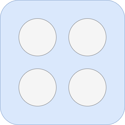
The Connection Node 4pin is a versatile electronic component designed to facilitate the interconnection of multiple circuit elements. It features four pins that can be used for signal or power distribution, making it an essential component in prototyping, breadboarding, and permanent circuit designs. Its compact design and ease of use make it suitable for a wide range of applications, from hobbyist projects to professional electronic systems.
Explore Projects Built with Connection Node 4pin

 Open Project in Cirkit Designer
 Open Project in Cirkit Designer
 Open Project in Cirkit Designer
 Open Project in Cirkit Designer
Explore Projects Built with Connection Node 4pin

 Open Project in Cirkit Designer
 Open Project in Cirkit Designer
 Open Project in Cirkit Designer
 Open Project in Cirkit Designer
Common Applications and Use Cases
- Signal distribution in multi-component circuits
- Power distribution for low-current devices
- Prototyping and testing circuits on breadboards
- Interfacing sensors, actuators, and microcontrollers
- Creating modular and reusable circuit designs
Technical Specifications
The following table outlines the key technical details of the Connection Node 4pin:
| Parameter | Value |
|---|---|
| Number of Pins | 4 |
| Maximum Voltage Rating | 30V DC |
| Maximum Current Rating | 2A per pin |
| Material | Plastic housing, metal pins |
| Pin Spacing | 2.54mm (standard breadboard spacing) |
| Operating Temperature | -40°C to 85°C |
Pin Configuration and Descriptions
The Connection Node 4pin has a simple pin layout, as described in the table below:
| Pin Number | Description |
|---|---|
| Pin 1 | Signal or power input/output |
| Pin 2 | Signal or power input/output |
| Pin 3 | Signal or power input/output |
| Pin 4 | Signal or power input/output |
Note: All pins are interchangeable and can be used for either signal or power, depending on the circuit design.
Usage Instructions
How to Use the Component in a Circuit
- Identify the Pins: The Connection Node 4pin has four identical pins. Determine which pins will be used for signal or power distribution based on your circuit requirements.
- Connect to a Breadboard or PCB: The 2.54mm pin spacing allows the component to be easily inserted into standard breadboards or soldered onto PCBs.
- Wire the Circuit: Use jumper wires or soldered connections to link the pins to other components in your circuit.
- Test the Circuit: Ensure all connections are secure and verify the circuit functionality before applying power.
Important Considerations and Best Practices
- Current Limitations: Do not exceed the maximum current rating of 2A per pin to avoid overheating or damage.
- Voltage Compatibility: Ensure the voltage applied to the pins does not exceed 30V DC.
- Avoid Short Circuits: Double-check connections to prevent accidental short circuits, which could damage the component or other parts of the circuit.
- Use with Microcontrollers: When connecting the Connection Node 4pin to a microcontroller like an Arduino UNO, ensure proper grounding and signal matching.
Example: Using the Connection Node 4pin with an Arduino UNO
Below is an example of how to use the Connection Node 4pin to distribute power and signals between an Arduino UNO and multiple LEDs:
// Example: Distributing power and signals using the Connection Node 4pin
// This code blinks two LEDs connected via the Connection Node 4pin

const int led1 = 2; // Pin 2 on Arduino connected to Pin 1 of the Connection Node
const int led2 = 3; // Pin 3 on Arduino connected to Pin 2 of the Connection Node

void setup() {
  pinMode(led1, OUTPUT); // Set pin 2 as output for LED 1
  pinMode(led2, OUTPUT); // Set pin 3 as output for LED 2
}

void loop() {
  digitalWrite(led1, HIGH); // Turn on LED 1
  digitalWrite(led2, HIGH); // Turn on LED 2
  delay(1000);              // Wait for 1 second

  digitalWrite(led1, LOW);  // Turn off LED 1
  digitalWrite(led2, LOW);  // Turn off LED 2
  delay(1000);              // Wait for 1 second
}
Tip: Use resistors in series with the LEDs to limit current and prevent damage.
Troubleshooting and FAQs
Common Issues Users Might Face
Loose Connections:
- Problem: The component does not make a secure connection with the breadboard or wires.
- Solution: Ensure the pins are fully inserted into the breadboard or soldered properly onto the PCB.
Overheating:
- Problem: The component becomes hot during operation.
- Solution: Check that the current through each pin does not exceed 2A. Reduce the load if necessary.
Signal Interference:
- Problem: Signals distributed through the Connection Node are noisy or unreliable.
- Solution: Use shorter wires and ensure proper grounding to minimize interference.
FAQs
Q: Can I use the Connection Node 4pin for AC signals?
A: While the component is primarily designed for DC circuits, it can handle low-frequency AC signals within the voltage and current ratings.
Q: Is the Connection Node 4pin suitable for high-power applications?
A: No, the component is designed for low-power applications with a maximum current rating of 2A per pin.
Q: Can I use all four pins for power distribution?
A: Yes, all four pins can be used for power distribution, but ensure the total current does not exceed the component's rating.
Q: How do I clean the component if it gets dirty?
A: Use a soft brush or compressed air to remove dust. Avoid using liquids that could damage the plastic housing or metal pins.
By following this documentation, users can effectively integrate the Connection Node 4pin into their electronic projects and troubleshoot common issues with ease.