How to Use 3 Pin LEDRocker Switch: Examples, Pinouts, and Specs
3-Pin LED Rocker Switch Documentation
1. Introduction
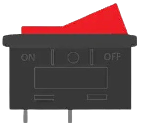
The 3-Pin LED Rocker Switch is a versatile and user-friendly component designed to control the flow of electricity in a circuit. It features a rocker mechanism for toggling between ON and OFF states and includes an integrated LED indicator to visually display the switch's status. This switch is widely used in various applications due to its simplicity, durability, and ease of installation.
Common Applications:
- Power control for electronic devices
- Automotive dashboards and control panels
- Home appliances and lighting systems
- DIY electronics projects
- Industrial equipment
The integrated LED indicator provides a clear visual cue, making it ideal for applications where the switch's status needs to be easily identified.
2. Technical Specifications
Below are the key technical details and pin configuration for the 3-Pin LED Rocker Switch:
Key Technical Details
| Parameter | Value |
|---|---|
| Operating Voltage | 12V DC (typical) |
| Current Rating | 6A @ 125V AC / 3A @ 250V AC |
| LED Voltage | 12V DC |
| Contact Resistance | ≤ 50 mΩ |
| Insulation Resistance | ≥ 100 MΩ |
| Operating Temperature | -25°C to +85°C |
| Mechanical Lifespan | 10,000 cycles |
| Mounting Hole Size | 20mm x 13mm (rectangular cutout) |
Pin Configuration and Descriptions
The 3-Pin LED Rocker Switch has three pins, as described in the table below:
| Pin Number | Label | Description |
|---|---|---|
| 1 | Load | Connects to the load (e.g., the device or circuit being powered). |
| 2 | Power | Connects to the positive terminal of the power supply. |
| 3 | Ground | Connects to the negative terminal of the power supply (also powers the LED). |
3. Usage Instructions
How to Use the 3-Pin LED Rocker Switch in a Circuit
Prepare the Circuit:
- Ensure the power supply is turned off before wiring the switch.
- Identify the load (device or circuit) you want to control with the switch.
Connect the Pins:
- Pin 1 (Load): Connect this pin to the positive terminal of the load.
- Pin 2 (Power): Connect this pin to the positive terminal of the power supply.
- Pin 3 (Ground): Connect this pin to the negative terminal of the power supply.
Mount the Switch:
- Insert the switch into a 20mm x 13mm rectangular cutout in your panel or enclosure.
- Ensure the switch is securely mounted to prevent movement during operation.
Test the Circuit:
- Turn on the power supply and toggle the switch to the ON position.
- Verify that the load is powered and the LED indicator lights up.
- Toggle the switch to the OFF position to ensure the load is disconnected.
Important Considerations and Best Practices
- Voltage Compatibility: Ensure the switch's voltage and current ratings match your circuit's requirements.
- LED Polarity: The LED indicator is polarity-sensitive. Ensure correct wiring of the power and ground pins.
- Heat Dissipation: Avoid exceeding the current rating to prevent overheating or damage to the switch.
- Secure Connections: Use soldering or crimp connectors for reliable and secure connections.
- Panel Mounting: Ensure the switch is properly mounted to avoid accidental toggling or disconnection.
4. Example Circuit with Arduino UNO
The 3-Pin LED Rocker Switch can be used with an Arduino UNO to control a simple LED circuit. Below is an example:
Circuit Diagram
- Pin 1 (Load): Connect to the positive terminal of the LED (via a 220Ω resistor).
- Pin 2 (Power): Connect to the Arduino's 5V pin.
- Pin 3 (Ground): Connect to the Arduino's GND pin.
Arduino Code Example
// Example code to use a 3-Pin LED Rocker Switch with Arduino UNO
// This code toggles an external LED based on the switch's state.

const int switchPin = 2;  // Pin connected to the switch's Load pin
const int ledPin = 13;    // Pin connected to the onboard LED

void setup() {
  pinMode(switchPin, INPUT);  // Set the switch pin as input
  pinMode(ledPin, OUTPUT);    // Set the LED pin as output
}

void loop() {
  int switchState = digitalRead(switchPin);  // Read the switch state

  if (switchState == HIGH) {
    digitalWrite(ledPin, HIGH);  // Turn on the LED if switch is ON
  } else {
    digitalWrite(ledPin, LOW);   // Turn off the LED if switch is OFF
  }
}
5. Troubleshooting and FAQs
Common Issues and Solutions
| Issue | Possible Cause | Solution |
|---|---|---|
| LED indicator does not light up | Incorrect wiring or reversed polarity | Verify the wiring and ensure correct polarity for the LED. |
| Switch does not control the load | Loose connections or incorrect pin usage | Check all connections and ensure the correct pins are used as per the table. |
| Switch overheats during operation | Exceeding current rating | Ensure the load does not exceed the switch's current rating. |
| Switch feels loose in the panel | Improper mounting | Securely mount the switch in the panel using the correct cutout dimensions. |
Frequently Asked Questions (FAQs)
Can I use the switch with a 24V power supply?
- Yes, but ensure the LED indicator is rated for 24V or use a resistor to limit the current.
Is the switch waterproof?
- Most 3-Pin LED Rocker Switches are not waterproof. Use a waterproof variant for outdoor applications.
Can I use the switch to control AC devices?
- Yes, the switch supports AC devices within its rated voltage and current limits.
What resistor value should I use for the LED?
- The integrated LED typically does not require an external resistor when used with a 12V supply.
This documentation provides a comprehensive guide to understanding, using, and troubleshooting the 3-Pin LED Rocker Switch. Whether you're a beginner or an experienced user, this guide will help you integrate the switch into your projects effectively.
Explore Projects Built with 3 Pin LEDRocker Switch
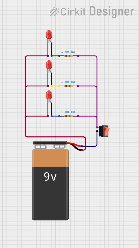
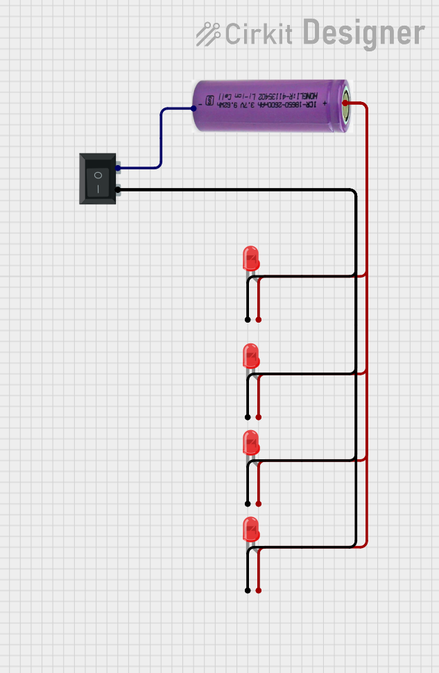
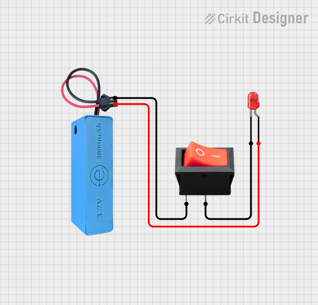

Explore Projects Built with 3 Pin LEDRocker Switch