How to Use iso : Examples, Pinouts, and Specs
Introduction
An isolator (ISO) is a device used in electrical circuits to separate different sections, ensuring electrical isolation between them. It prevents unwanted current flow, protects sensitive components from high voltages, and reduces noise interference. Isolators are commonly used in industrial automation, medical devices, power systems, and communication circuits to enhance safety and signal integrity.
Explore Projects Built with iso

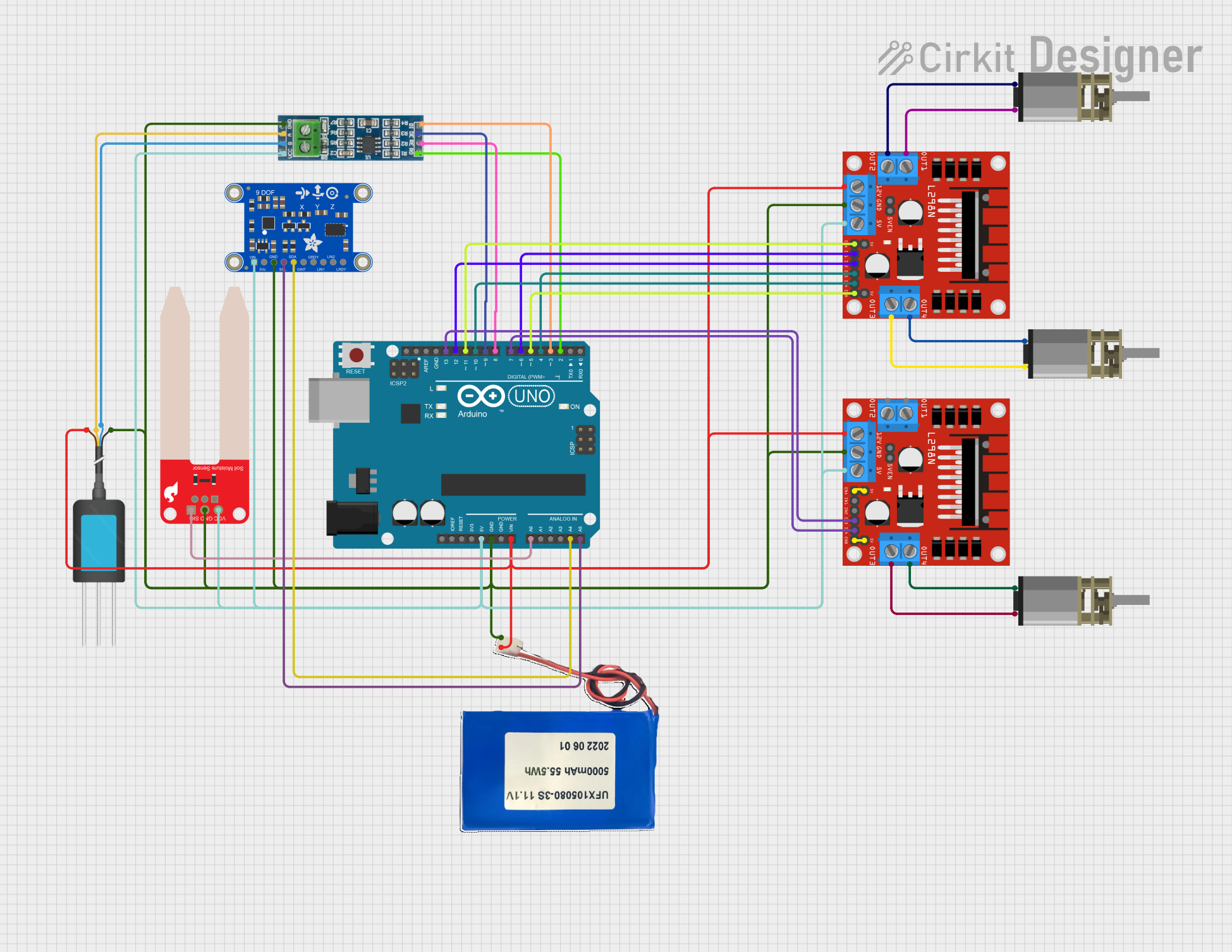
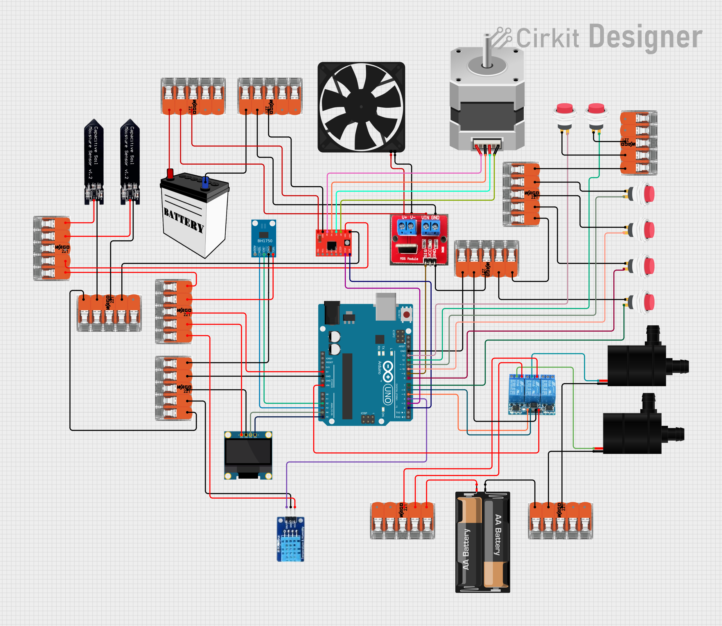
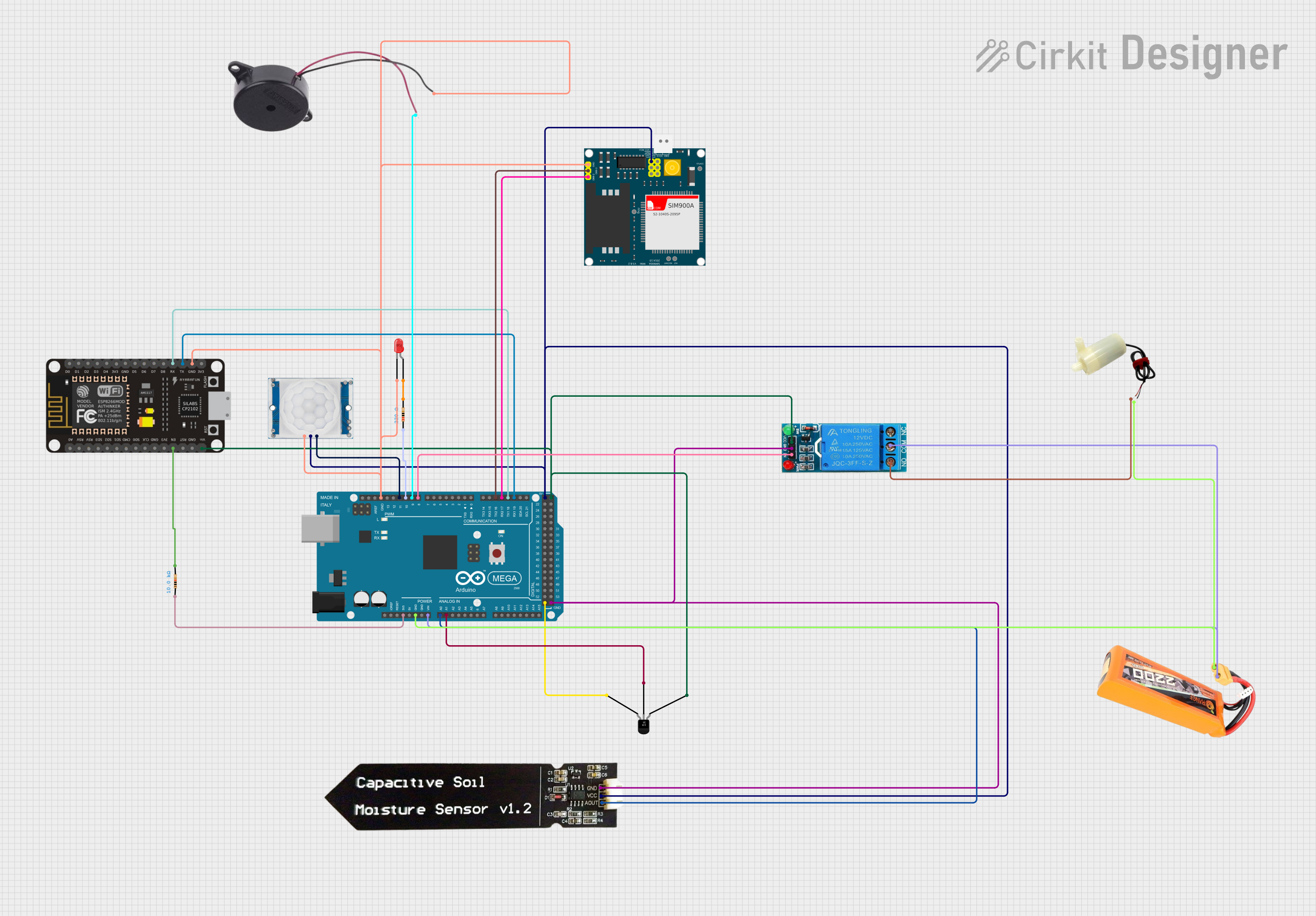
Explore Projects Built with iso
Common Applications and Use Cases
- Industrial Automation: Protects control systems from high-voltage equipment.
- Medical Devices: Ensures patient safety by isolating sensitive electronics.
- Power Systems: Prevents ground loops and isolates high-voltage sections.
- Communication Systems: Reduces noise and interference in signal transmission.
Technical Specifications
Below are the general technical specifications for a typical isolator. Specific values may vary depending on the model and manufacturer.
Key Technical Details
- Isolation Voltage: Up to 5 kV (varies by model)
- Operating Voltage: 3.3V to 5V (logic-level isolators)
- Data Rate: Up to 150 Mbps (for digital isolators)
- Propagation Delay: Typically 10 ns to 50 ns
- Power Consumption: 1 mW to 10 mW (depending on the application)
- Temperature Range: -40°C to +125°C
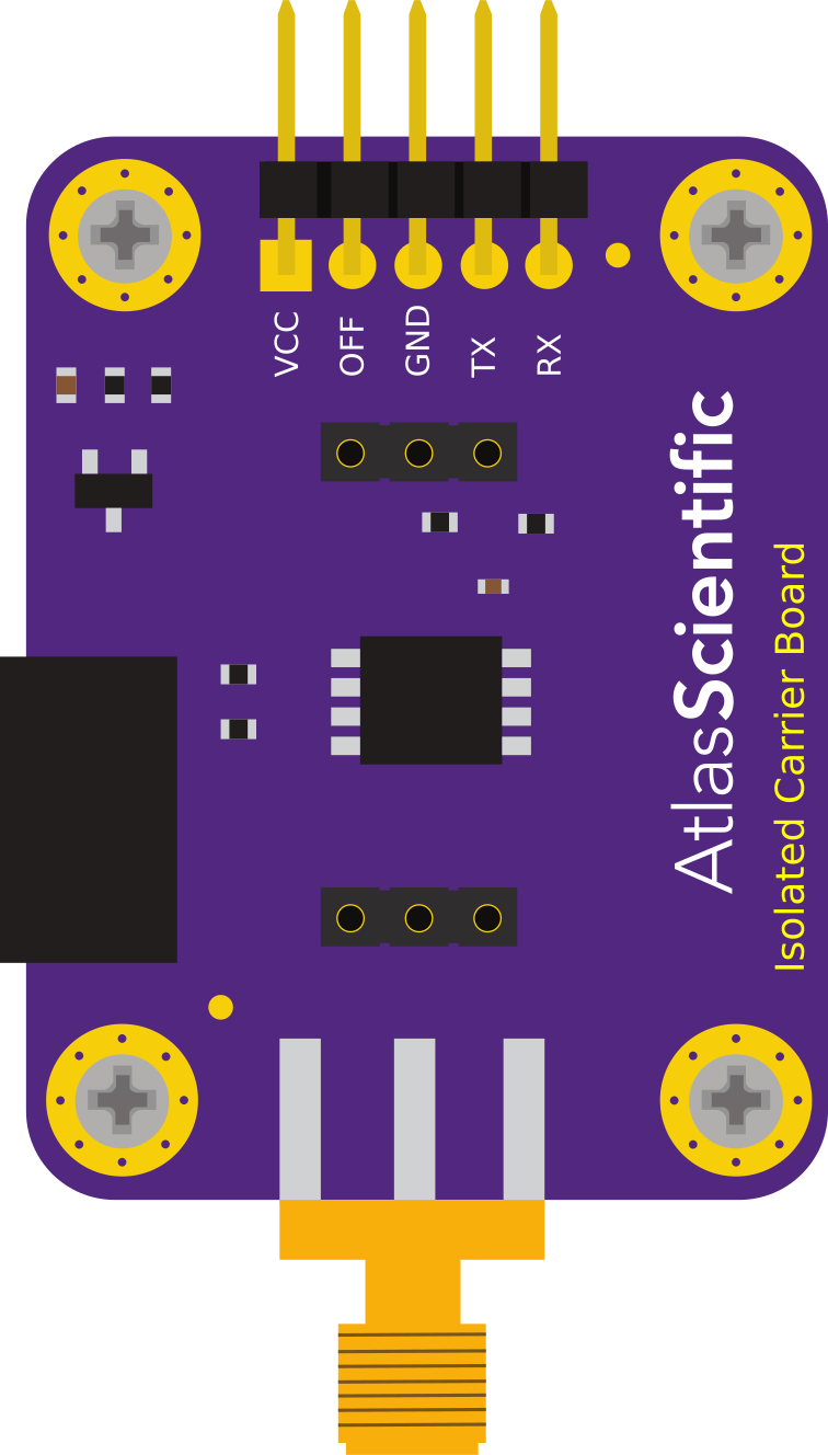
Pin Configuration and Descriptions
The pin configuration for a common 8-pin digital isolator is shown below:
| Pin | Name | Description |
|---|---|---|
| 1 | VDD1 | Power supply for the input side of the isolator |
| 2 | GND1 | Ground for the input side |
| 3 | IN1 | Input signal 1 |
| 4 | IN2 | Input signal 2 |
| 5 | OUT2 | Output signal 2 (isolated from input side) |
| 6 | OUT1 | Output signal 1 (isolated from input side) |
| 7 | GND2 | Ground for the output side |
| 8 | VDD2 | Power supply for the output side of the isolator |
Note: The pinout may vary depending on the specific isolator model. Always refer to the manufacturer's datasheet for exact details.
Usage Instructions
How to Use the Component in a Circuit
- Power Supply: Connect the input side (VDD1, GND1) and output side (VDD2, GND2) to separate power supplies to ensure proper isolation.
- Signal Connections:
- Connect the input signals (e.g., IN1, IN2) to the input pins of the isolator.
- The corresponding isolated output signals will appear on the output pins (e.g., OUT1, OUT2).
- Bypass Capacitors: Place decoupling capacitors (e.g., 0.1 µF) close to the VDD1 and VDD2 pins to reduce noise and ensure stable operation.
- PCB Layout: Maintain sufficient spacing between the input and output sides on the PCB to preserve isolation integrity.
Important Considerations and Best Practices
- Isolation Voltage: Ensure the isolator's isolation voltage rating exceeds the maximum voltage difference between the input and output sides.
- Signal Integrity: Use proper termination resistors for high-speed signals to minimize reflections and noise.
- Thermal Management: If the isolator operates in a high-temperature environment, ensure adequate cooling or heat dissipation.
- Testing: Verify the isolation barrier using appropriate test equipment before deploying the circuit.
Example: Connecting an Isolator to an Arduino UNO
Below is an example of using a digital isolator to protect an Arduino UNO from high-voltage signals.
Circuit Description
- The isolator separates the Arduino's low-voltage logic from a high-voltage sensor.
- The input side of the isolator is connected to the sensor, while the output side interfaces with the Arduino.
Arduino Code Example
// Example: Reading a signal through an isolator
// The isolator's output is connected to Arduino pin 2

const int isoInputPin = 2; // Pin connected to the isolator's output
void setup() {
  pinMode(isoInputPin, INPUT); // Set the pin as input
  Serial.begin(9600); // Initialize serial communication
}

void loop() {
  int signal = digitalRead(isoInputPin); // Read the signal from the isolator
  Serial.print("Isolated Signal: ");
  Serial.println(signal); // Print the signal value to the Serial Monitor
  delay(500); // Wait for 500 ms before reading again
}
Note: Ensure the isolator's output voltage levels are compatible with the Arduino's input voltage levels (e.g., 5V or 3.3V).
Troubleshooting and FAQs
Common Issues and Solutions
No Output Signal:
- Cause: Power supply not connected to both sides of the isolator.
- Solution: Verify that VDD1, GND1, VDD2, and GND2 are properly connected.
Signal Distortion:
- Cause: High-speed signals not properly terminated.
- Solution: Add termination resistors to match the characteristic impedance of the signal lines.
Excessive Noise:
- Cause: Insufficient decoupling capacitors.
- Solution: Place 0.1 µF capacitors close to the VDD pins on both sides of the isolator.
Overheating:
- Cause: Operating the isolator beyond its rated voltage or current.
- Solution: Ensure the isolator is used within its specified limits.
FAQs
Q: Can I use a single power supply for both sides of the isolator?
A: No, using a single power supply defeats the purpose of isolation. Separate power supplies are required.Q: How do I test the isolation barrier?
A: Use a high-voltage tester to apply the rated isolation voltage between the input and output sides and check for leakage current.Q: Can isolators handle analog signals?
A: Some isolators are designed for analog signals, but most are optimized for digital signals. Check the datasheet for compatibility.Q: What is the difference between an isolator and an optocoupler?
A: An isolator can use various technologies (e.g., capacitive, magnetic, or optical) for isolation, while an optocoupler specifically uses light for isolation.
By following this documentation, you can effectively integrate an isolator into your circuit and ensure reliable operation. Always consult the manufacturer's datasheet for specific details about your isolator model.