
How to Use Adafruit 1.44 inch TFT Breakout: Examples, Pinouts, and Specs
 Design with Adafruit 1.44 inch TFT Breakout in Cirkit Designer
Introduction
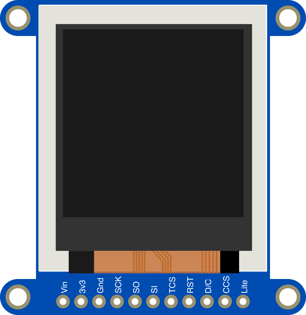
The Adafruit 1.44 inch TFT Breakout (Manufacturer Part ID: 2088) is a compact color display module featuring a 1.44-inch TFT LCD screen. It is designed for projects requiring vibrant visual output and supports SPI communication for efficient data transfer. This module is compatible with a wide range of microcontrollers, including Arduino, Raspberry Pi, and other embedded systems, making it an excellent choice for applications such as graphical interfaces, data visualization, and compact user interfaces.
Explore Projects Built with Adafruit 1.44 inch TFT Breakout
 Open Project in Cirkit Designer
 Open Project in Cirkit Designer
 Open Project in Cirkit Designer
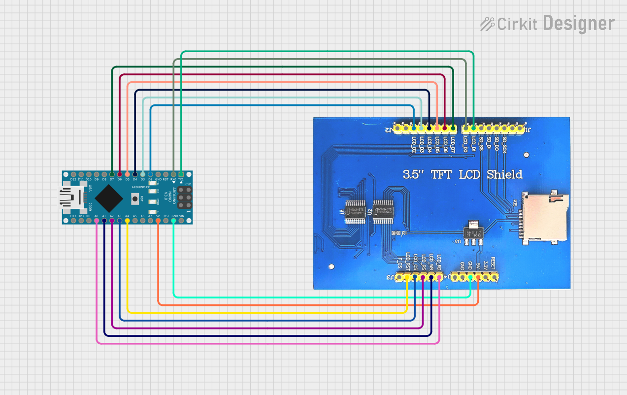 Open Project in Cirkit Designer
Explore Projects Built with Adafruit 1.44 inch TFT Breakout
Open Project in Cirkit DesignerOpen Project in Cirkit DesignerOpen Project in Cirkit DesignerOpen Project in Cirkit DesignerCommon Applications
- Portable devices with graphical displays
- Embedded systems requiring visual feedback
- Data visualization for sensors and IoT projects
- Custom user interfaces for DIY electronics
- Educational projects and prototyping
Technical Specifications
Below are the key technical details of the Adafruit 1.44 inch TFT Breakout:
| Specification | Details |
|---|---|
| Screen Size | 1.44 inches |
| Resolution | 128 x 128 pixels |
| Display Type | TFT LCD with full 18-bit color (262,144 colors) |
| Communication Interface | SPI (Serial Peripheral Interface) |
| Operating Voltage | 3.3V logic level (5V-tolerant with onboard level shifter) |
| Backlight | LED backlight with adjustable brightness |
| Current Consumption | ~40mA (varies with backlight brightness) |
| Dimensions | 40mm x 40mm x 6mm |
| Weight | 8g |
Pin Configuration and Descriptions
The Adafruit 1.44 inch TFT Breakout has the following pinout:
| Pin Name | Description |
|---|---|
| VIN | Power input (3.3V to 5V) |
| GND | Ground connection |
| SCK | SPI Clock (connect to microcontroller's SPI clock pin) |
| MOSI | SPI Master Out Slave In (connect to microcontroller's SPI MOSI pin) |
| CS | Chip Select (active low, used to select the display) |
| DC | Data/Command (used to differentiate between data and command instructions) |
| RST | Reset (active low, used to reset the display) |
| BL | Backlight control (PWM-capable pin for brightness adjustment) |
Usage Instructions
Connecting the Display to an Arduino UNO
To use the Adafruit 1.44 inch TFT Breakout with an Arduino UNO, follow these steps:
Wiring the Display:
- Connect the VIN pin to the Arduino's 5V pin.
- Connect the GND pin to the Arduino's GND pin.
- Connect the SCK pin to the Arduino's D13 pin (SPI clock).
- Connect the MOSI pin to the Arduino's D11 pin (SPI MOSI).
- Connect the CS pin to the Arduino's D10 pin.
- Connect the DC pin to the Arduino's D9 pin.
- Connect the RST pin to the Arduino's D8 pin.
- Optionally, connect the BL pin to a PWM-capable pin (e.g., D6) for backlight control.
Install Required Libraries:
- Download and install the Adafruit_GFX and Adafruit_ST7735 libraries from the Arduino Library Manager.
Example Code: Use the following example code to initialize the display and draw basic graphics:
// Include necessary libraries
#include <Adafruit_GFX.h>       // Core graphics library
#include <Adafruit_ST7735.h>    // Library for ST7735 TFT display

// Define pins for the display
#define TFT_CS     10  // Chip Select pin
#define TFT_RST    8   // Reset pin
#define TFT_DC     9   // Data/Command pin

// Initialize the display object
Adafruit_ST7735 tft = Adafruit_ST7735(TFT_CS, TFT_DC, TFT_RST);

void setup() {
  // Initialize the display
  tft.initR(INITR_144GREENTAB);  // Initialize with 1.44" green tab settings
  tft.fillScreen(ST77XX_BLACK); // Clear the screen with black color

  // Display a message
  tft.setTextColor(ST77XX_WHITE); // Set text color to white
  tft.setTextSize(1);             // Set text size
  tft.setCursor(0, 0);            // Set cursor position
  tft.println("Hello, TFT!");     // Print text to the screen
}

void loop() {
  // Add your code here for dynamic updates
}
Important Considerations
- Voltage Levels: The display operates at 3.3V logic levels but is 5V-tolerant due to the onboard level shifter. Ensure proper connections to avoid damage.
- Backlight Control: Use a PWM-capable pin to adjust the backlight brightness for power efficiency.
- SPI Speed: For optimal performance, configure the SPI clock speed appropriately in your microcontroller's settings.
Troubleshooting and FAQs
Common Issues and Solutions
Display Not Turning On:
- Ensure the VIN and GND pins are properly connected.
- Verify that the power supply provides sufficient voltage (3.3V to 5V).
No Output on the Screen:
- Check the SPI connections (SCK, MOSI, CS, DC, RST).
- Ensure the correct pins are defined in the code.
- Verify that the Adafruit_GFX and Adafruit_ST7735 libraries are installed.
Flickering or Unstable Display:
- Reduce the SPI clock speed in the microcontroller settings.
- Ensure stable power supply and proper grounding.
Backlight Not Working:
- Check the connection to the BL pin.
- If using PWM for brightness control, ensure the pin supports PWM output.
FAQs
Q: Can I use this display with a Raspberry Pi?
A: Yes, the display is compatible with Raspberry Pi. Use the SPI interface and configure the pins in your Raspberry Pi's software.
Q: What is the maximum SPI clock speed supported?
A: The display supports SPI clock speeds up to 15 MHz. However, lower speeds may be required for stable operation depending on your setup.
Q: Can I use this display in outdoor environments?
A: The display is not sunlight-readable and is best suited for indoor use or shaded environments.
Q: How do I display images on the screen?
A: Use the Adafruit_GFX library's bitmap functions to load and display images. Convert images to a compatible format (e.g., 24-bit BMP) before use.
By following this documentation, you can effectively integrate the Adafruit 1.44 inch TFT Breakout into your projects and troubleshoot common issues.