How to Use 20 Pin Board: Examples, Pinouts, and Specs
Introduction
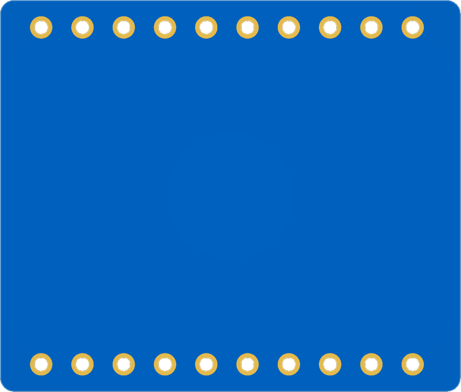
- The 20 Pin Board is a versatile prototyping board designed for assembling and testing electronic circuits. It features 20 pins that allow for easy connection of various components, making it ideal for rapid prototyping and experimentation.
- Common applications include:
- Building and testing small-scale circuits.
- Prototyping microcontroller-based projects.
- Educational purposes for learning circuit design and assembly.
- Temporary setups for debugging and troubleshooting circuits.
Explore Projects Built with 20 Pin Board


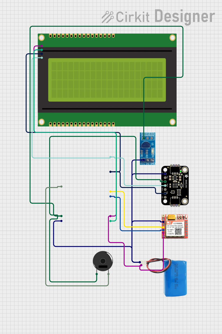
Explore Projects Built with 20 Pin Board
Technical Specifications
- Manufacturer: None
- Part ID: Board
- Description: A prototyping board with 20 pins for connecting electronic components.
Key Technical Details
| Parameter | Value |
|---|---|
| Number of Pins | 20 |
| Pin Type | Male or Female (varies) |
| Board Material | FR4 (standard PCB material) |
| Pin Spacing | 2.54 mm (0.1 inch) standard |
| Dimensions | Varies (e.g., 50mm x 20mm) |
| Operating Temperature | -40°C to +85°C |
| Maximum Current (per pin) | 1A |
| Maximum Voltage (per pin) | 50V |
Pin Configuration and Descriptions
The 20 Pin Board does not have a predefined pin configuration, as it is a general-purpose prototyping board. However, the pins are typically arranged in a single or dual row, with a standard 2.54 mm spacing. Below is an example of a dual-row pin layout:
| Pin Number | Description |
|---|---|
| 1-10 | Row 1: General-purpose pins |
| 11-20 | Row 2: General-purpose pins |
Note: The actual pin usage depends on the circuit design and components connected to the board.
Usage Instructions
How to Use the 20 Pin Board in a Circuit
- Plan Your Circuit: Sketch the circuit diagram and identify the components you will use.
- Insert Components: Place components such as resistors, capacitors, ICs, or wires into the pins of the board.
- Connect Pins: Use jumper wires or solder connections to link the pins as per your circuit design.
- Power the Circuit: Connect a power source to the appropriate pins, ensuring the voltage and current are within the board's specifications.
- Test the Circuit: Verify the functionality of your circuit using a multimeter or oscilloscope.
Important Considerations and Best Practices
- Avoid Overloading: Do not exceed the maximum current (1A) or voltage (50V) per pin to prevent damage.
- Secure Connections: Ensure all connections are tight and secure to avoid intermittent issues.
- Use Proper Tools: Use a soldering iron with appropriate temperature settings if soldering is required.
- Label Pins: For complex circuits, label the pins to avoid confusion during assembly and testing.
- Static Precautions: Handle the board and components with care to avoid damage from electrostatic discharge (ESD).
Example: Connecting to an Arduino UNO
The 20 Pin Board can be used to expand the I/O capabilities of an Arduino UNO. Below is an example of connecting LEDs to the board and controlling them with the Arduino:
Circuit Setup
- Connect the 20 Pin Board to the Arduino UNO using jumper wires.
- Attach LEDs to pins 1-5 of the board, with current-limiting resistors in series.
- Connect the ground pin of the board to the Arduino's GND.
Arduino Code
// Example code to control LEDs connected to a 20 Pin Board
// Pins 1-5 on the board are connected to Arduino digital pins 2-6

void setup() {
  // Set Arduino pins 2-6 as outputs
  for (int pin = 2; pin <= 6; pin++) {
    pinMode(pin, OUTPUT);
  }
}

void loop() {
  // Turn LEDs on sequentially
  for (int pin = 2; pin <= 6; pin++) {
    digitalWrite(pin, HIGH); // Turn LED on
    delay(500);              // Wait for 500ms
    digitalWrite(pin, LOW);  // Turn LED off
  }
}
Troubleshooting and FAQs
Common Issues
- Loose Connections: Components or wires may not be securely connected to the pins.
- Solution: Double-check all connections and ensure they are tight.
- Overheating: The board or components may overheat if the current or voltage exceeds the limits.
- Solution: Verify that the power supply is within the specified range.
- Intermittent Circuit Behavior: The circuit may behave unpredictably due to poor connections or faulty components.
- Solution: Inspect the board for loose wires, cold solder joints, or damaged components.
FAQs
Q: Can I use the 20 Pin Board for high-power applications?
A: No, the board is designed for low-power circuits with a maximum current of 1A per pin.Q: Is the board reusable?
A: Yes, the board can be reused multiple times if components are not permanently soldered.Q: Can I use the board with microcontrollers other than Arduino?
A: Yes, the board is compatible with any microcontroller or development board that supports standard pin spacing (2.54 mm).Q: How do I clean the board after soldering?
A: Use isopropyl alcohol and a soft brush to remove flux residue and keep the board clean.
By following this documentation, users can effectively utilize the 20 Pin Board for their prototyping and circuit design needs.