Cirkit Designer Logo
Cirkit Designer
Your all-in-one circuit design IDE
Home / 
Component Documentation

How to Use Relay Module 2 Channel: Examples, Pinouts, and Specs

Image of Relay Module 2 Channel
Cirkit Designer LogoDesign with Relay Module 2 Channel in Cirkit Designer

Introduction

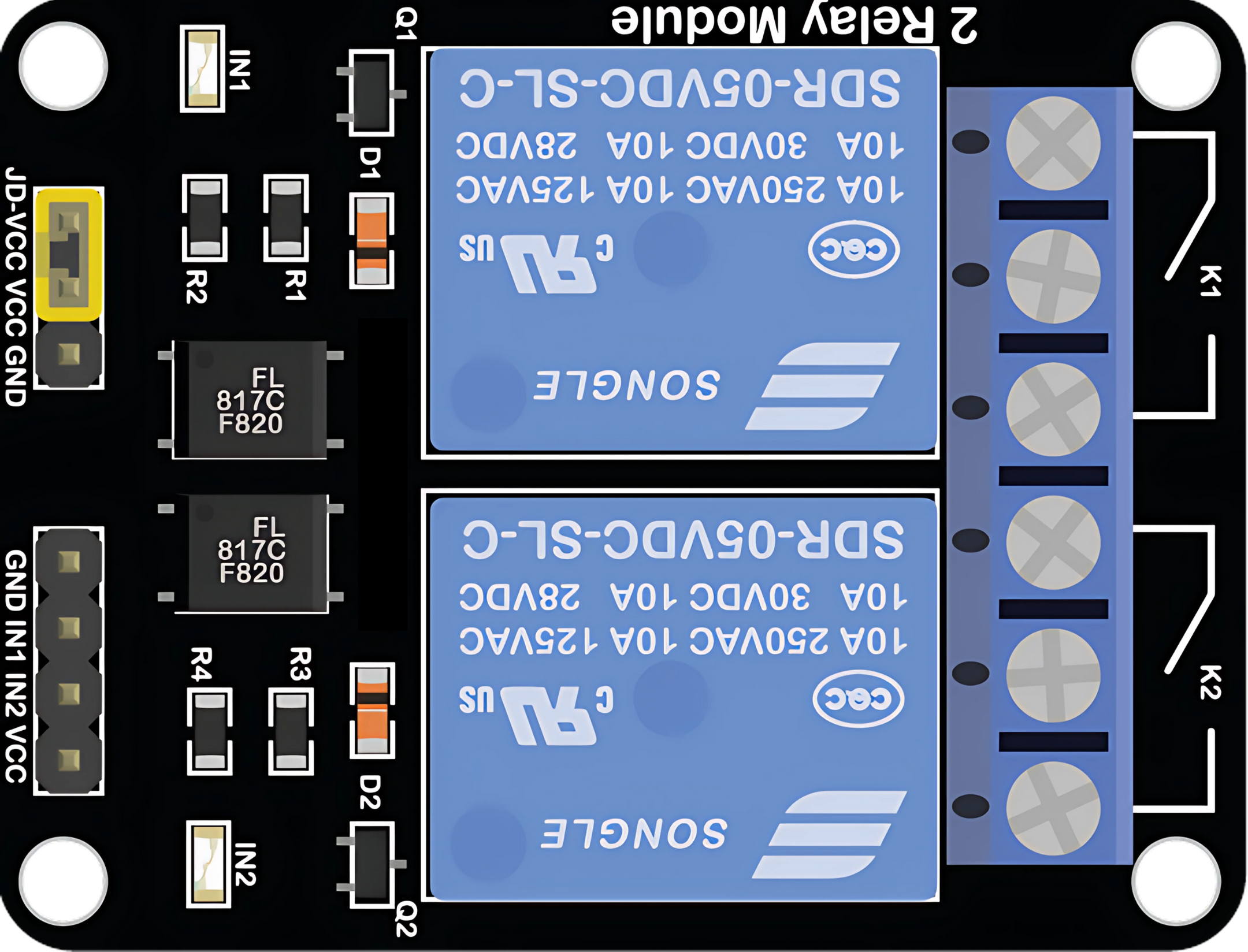
A Relay Module 2 Channel is an electronic device that enables control of high voltage and high current loads with low voltage signals, typically from a microcontroller like an Arduino. This module contains two independent relays that can switch on and off separately. It is commonly used in home automation, industrial controls, and other applications where interfacing between low-level logic and high-power devices is required.

Explore Projects Built with Relay Module 2 Channel

Use Cirkit Designer to design, explore, and prototype these projects online. Some projects support real-time simulation. Click "Open Project" to start designing instantly!
DC-DC Converter and Relay Module Power Distribution System
Image of relay: A project utilizing Relay Module 2 Channel in a practical application
This circuit consists of a DC-DC converter powering a 6-channel power module, which in turn supplies 5V to a 2-relay module. The power module distributes the converted voltage to the relay module, enabling it to control external devices.
Cirkit Designer LogoOpen Project in Cirkit Designer
Battery-Powered 4-Channel Relay Control with LED Indicators
Image of RELLAY BOARD TEST: A project utilizing Relay Module 2 Channel in a practical application
This circuit consists of a 5V battery powering a 4-channel relay module, which controls four LEDs (red, yellow, green, and blue) through individual resistors. Each relay channel is activated by a corresponding SPST toggle switch, allowing manual control of the LEDs.
Cirkit Designer LogoOpen Project in Cirkit Designer
ESP32-Powered 8-Channel Relay Controller with Wi-Fi Connectivity
Image of Olimex ESP32-POE2 4Ch X 2 Switches: A project utilizing Relay Module 2 Channel in a practical application
This circuit features an ESP32 microcontroller connected to an 8-channel relay module. The ESP32 controls the relay channels via its GPIO pins, allowing for the switching of external devices or loads through the relays.
Cirkit Designer LogoOpen Project in Cirkit Designer
ESP32 Wi-Fi Controlled Dual Relay Module
Image of esp: A project utilizing Relay Module 2 Channel in a practical application
This circuit features an ESP32 microcontroller connected to a two-channel 5V relay module. The ESP32 controls the relay channels via its GPIO pins D23 and D22, allowing it to switch external devices on and off. The relay module is powered by the 3.3V and GND pins of the ESP32.
Cirkit Designer LogoOpen Project in Cirkit Designer

Explore Projects Built with Relay Module 2 Channel

Use Cirkit Designer to design, explore, and prototype these projects online. Some projects support real-time simulation. Click "Open Project" to start designing instantly!
Image of relay: A project utilizing Relay Module 2 Channel in a practical application
DC-DC Converter and Relay Module Power Distribution System
This circuit consists of a DC-DC converter powering a 6-channel power module, which in turn supplies 5V to a 2-relay module. The power module distributes the converted voltage to the relay module, enabling it to control external devices.
Cirkit Designer LogoOpen Project in Cirkit Designer
Image of RELLAY BOARD TEST: A project utilizing Relay Module 2 Channel in a practical application
Battery-Powered 4-Channel Relay Control with LED Indicators
This circuit consists of a 5V battery powering a 4-channel relay module, which controls four LEDs (red, yellow, green, and blue) through individual resistors. Each relay channel is activated by a corresponding SPST toggle switch, allowing manual control of the LEDs.
Cirkit Designer LogoOpen Project in Cirkit Designer
Image of Olimex ESP32-POE2 4Ch X 2 Switches: A project utilizing Relay Module 2 Channel in a practical application
ESP32-Powered 8-Channel Relay Controller with Wi-Fi Connectivity
This circuit features an ESP32 microcontroller connected to an 8-channel relay module. The ESP32 controls the relay channels via its GPIO pins, allowing for the switching of external devices or loads through the relays.
Cirkit Designer LogoOpen Project in Cirkit Designer
Image of esp: A project utilizing Relay Module 2 Channel in a practical application
ESP32 Wi-Fi Controlled Dual Relay Module
This circuit features an ESP32 microcontroller connected to a two-channel 5V relay module. The ESP32 controls the relay channels via its GPIO pins D23 and D22, allowing it to switch external devices on and off. The relay module is powered by the 3.3V and GND pins of the ESP32.
Cirkit Designer LogoOpen Project in Cirkit Designer

Common Applications and Use Cases

  • Home automation systems (e.g., controlling lights, fans, or heating)
  • Industrial machine control
  • Remote control of high-power circuits
  • Automotive electronics for controlling lights, alarms, etc.

Technical Specifications

Key Technical Details

  • Operating Voltage (VCC): 5V DC
  • Trigger Voltage (IN1, IN2): 0-5V DC
  • Max Switching Voltage: 250V AC / 30V DC
  • Max Switching Current: 10A per channel
  • Relay Type: Electromechanical
  • Number of Channels: 2
  • Isolation: Opto-isolated inputs

Pin Configuration and Descriptions

Pin Description
VCC Connect to 5V power supply
GND Connect to ground
IN1 Control signal for Relay 1 (active LOW)
IN2 Control signal for Relay 2 (active LOW)
NO1 Normally Open contact for Relay 1
NC1 Normally Closed contact for Relay 1
COM1 Common contact for Relay 1
NO2 Normally Open contact for Relay 2
NC2 Normally Closed contact for Relay 2
COM2 Common contact for Relay 2

Usage Instructions

How to Use the Component in a Circuit

  1. Connect the VCC pin to a 5V power supply.
  2. Connect the GND pin to the ground of the power supply.
  3. Connect the IN1 and IN2 pins to the digital outputs of a microcontroller.
  4. Connect the device you want to control to the NO or NC and COM pins of the relay.

Important Considerations and Best Practices

  • Ensure the power supply can deliver sufficient current for the relay coil.
  • Do not exceed the maximum switching voltage and current ratings.
  • Use flyback diodes across inductive loads to prevent back EMF damage.
  • Consider using a separate power supply for the relay coils to prevent noise in the microcontroller circuit.

Example Code for Arduino UNO

// Define relay control pins
const int relayPin1 = 2;
const int relayPin2 = 3;

void setup() {
  // Set relay pins as output
  pinMode(relayPin1, OUTPUT);
  pinMode(relayPin2, OUTPUT);

  // Initialize relays to OFF (Relays are active LOW)
  digitalWrite(relayPin1, HIGH);
  digitalWrite(relayPin2, HIGH);
}

void loop() {
  // Turn on Relay 1
  digitalWrite(relayPin1, LOW);
  delay(1000); // Wait for 1 second

  // Turn off Relay 1
  digitalWrite(relayPin1, HIGH);
  delay(1000); // Wait for 1 second

  // Turn on Relay 2
  digitalWrite(relayPin2, LOW);
  delay(1000); // Wait for 1 second

  // Turn off Relay 2
  digitalWrite(relayPin2, HIGH);
  delay(1000); // Wait for 1 second
}

Troubleshooting and FAQs

Common Issues Users Might Face

  • Relay not activating: Check the control signal voltage and connections.
  • Intermittent operation: Ensure a stable power supply and check for loose connections.
  • Clicking sound but no switching: Verify the load does not exceed the relay's rating.

Solutions and Tips for Troubleshooting

  • Always double-check wiring, especially the load's power connections.
  • Test the relay module with a multimeter to ensure proper function.
  • If using inductive loads, make sure to use flyback diodes to protect the relay contacts.

FAQs

Q: Can I control the relay module with a 3.3V signal? A: While the relay module is designed for 5V logic, some modules may work with 3.3V signals. Check the module's datasheet or test it with a 3.3V signal.

Q: How can I know if the relay is in the NO or NC state? A: When the relay is not powered, the NO contact is open, and the NC contact is closed. Applying a LOW signal to the IN pin will switch the relay to the opposite state.

Q: Is it safe to switch AC loads with this relay module? A: Yes, as long as the load does not exceed the maximum voltage and current ratings of the relay. Always follow safety precautions when working with AC mains.