How to Use mini power bank module: Examples, Pinouts, and Specs
Introduction
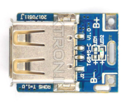
The Mini Power Bank Module is a compact and efficient device designed to store electrical energy and provide a portable power source for charging electronic devices such as smartphones, tablets, and other USB-powered gadgets. It is an essential component for building custom power banks or integrating portable charging functionality into DIY projects. Its small size and versatility make it ideal for hobbyists, engineers, and makers.
Explore Projects Built with mini power bank module


Explore Projects Built with mini power bank module
Common Applications and Use Cases
- DIY portable power banks
- Emergency backup power for small devices
- Integration into custom electronic projects
- Educational projects to demonstrate energy storage and power delivery
- Powering low-power IoT devices on the go
Technical Specifications
Below are the key technical details of the Mini Power Bank Module:
| Parameter | Specification |
|---|---|
| Input Voltage | 5V DC (via micro-USB or Type-C port) |
| Output Voltage | 5V DC (via USB-A port) |
| Output Current | Up to 1A |
| Battery Compatibility | 3.7V Li-ion or LiPo battery |
| Charging Current | 1A (max) |
| Efficiency | Up to 92% |
| Dimensions | ~25mm x 15mm x 5mm |
| Protection Features | Overcharge, over-discharge, short-circuit protection |
Pin Configuration and Descriptions
The Mini Power Bank Module typically has the following pins and connectors:
| Pin/Connector | Description |
|---|---|
| Micro-USB Port | Input port for charging the connected battery using a 5V DC power source. |
| Type-C Port | Alternative input port for charging the battery (if available). |
| USB-A Port | Output port for powering or charging external devices. |
| B+ | Positive terminal for connecting the 3.7V Li-ion/LiPo battery. |
| B- | Negative terminal for connecting the 3.7V Li-ion/LiPo battery. |
| Indicator LEDs | Status LEDs to indicate charging, discharging, or fault conditions. |
Usage Instructions
How to Use the Mini Power Bank Module in a Circuit
- Connect the Battery:
- Attach a 3.7V Li-ion or LiPo battery to the
B+(positive) andB-(negative) terminals of the module. Ensure correct polarity to avoid damage.
- Attach a 3.7V Li-ion or LiPo battery to the
- Charge the Battery:
- Use a 5V DC power source (e.g., a USB charger) to charge the battery via the micro-USB or Type-C input port. The module's built-in charging circuit will handle the process.
- Power External Devices:
- Connect your device to the USB-A output port. The module will regulate the battery's voltage to provide a stable 5V output.
- Monitor Status:
- Observe the indicator LEDs for charging, discharging, or fault status:
- Red LED: Charging in progress.
- Blue LED: Fully charged or discharging.
- Flashing LED: Fault condition (e.g., short circuit or overcurrent).
- Observe the indicator LEDs for charging, discharging, or fault status:
Important Considerations and Best Practices
- Battery Selection: Use only high-quality 3.7V Li-ion or LiPo batteries with appropriate capacity and discharge ratings.
- Heat Management: Avoid operating the module in high-temperature environments to prevent overheating.
- Load Limitations: Do not exceed the maximum output current (1A) to ensure safe operation.
- Polarity Check: Double-check battery polarity before connecting to avoid damage to the module.
- Secure Connections: Ensure all connections are secure to prevent accidental disconnections during operation.
Example: Using the Mini Power Bank Module with an Arduino UNO
The Mini Power Bank Module can be used to power an Arduino UNO in portable projects. Below is an example:
- Connect a 3.7V Li-ion battery to the module's
B+andB-terminals. - Use a USB cable to connect the module's USB-A output port to the Arduino UNO's USB input port.
- The Arduino UNO will receive a stable 5V supply from the module.
Here is a simple Arduino sketch to blink an LED while powered by the Mini Power Bank Module:
// Blink an LED connected to pin 13
// This sketch demonstrates the Arduino UNO running on power
// supplied by the Mini Power Bank Module.

void setup() {
  pinMode(13, OUTPUT); // Set pin 13 as an output pin
}

void loop() {
  digitalWrite(13, HIGH); // Turn the LED on
  delay(1000);            // Wait for 1 second
  digitalWrite(13, LOW);  // Turn the LED off
  delay(1000);            // Wait for 1 second
}
Troubleshooting and FAQs
Common Issues and Solutions
Module Not Powering On:
- Ensure the battery is properly connected with correct polarity.
- Check if the battery is charged. Recharge if necessary.
- Verify the input voltage is 5V when charging via USB.
No Output from USB Port:
- Confirm the connected device does not exceed the 1A output current limit.
- Check for loose connections or damaged cables.
Overheating:
- Avoid using the module in high-temperature environments.
- Ensure the load does not exceed the module's rated output current.
LED Indicators Not Working:
- Verify the battery connection and charge level.
- Inspect the module for physical damage or manufacturing defects.
FAQs
Q1: Can I use a higher voltage battery with this module?
No, the module is designed specifically for 3.7V Li-ion or LiPo batteries. Using a higher voltage battery may damage the module.
Q2: Can I charge the battery and power a device simultaneously?
Yes, the module supports pass-through charging, allowing you to charge the battery while powering an external device.
Q3: What happens if I connect the battery with reversed polarity?
The module may be permanently damaged. Always double-check the polarity before connecting the battery.
Q4: Can I use this module to power high-current devices like tablets?
The module is limited to a maximum output current of 1A. It may not be suitable for high-current devices.
By following this documentation, you can effectively use the Mini Power Bank Module in your projects and troubleshoot common issues.