Cirkit Designer Logo
Cirkit Designer
Your all-in-one circuit design IDE
Home / 
Component Documentation

How to Use ICM20948: Examples, Pinouts, and Specs

Image of ICM20948
Cirkit Designer LogoDesign with ICM20948 in Cirkit Designer

Introduction

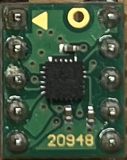
The ICM20948, manufactured by InvenSense, is a highly integrated 9-axis motion tracking device. It combines a 3-axis gyroscope, a 3-axis accelerometer, and a 3-axis magnetometer into a single compact chip. This component is designed for applications requiring precise motion and orientation sensing, such as robotics, drones, smartphones, wearable devices, and gaming controllers.

The ICM20948 is known for its low power consumption, high accuracy, and advanced features like Digital Motion Processing™ (DMP) for sensor fusion. It communicates via I²C or SPI interfaces, making it versatile and easy to integrate into a wide range of systems.

Explore Projects Built with ICM20948

Use Cirkit Designer to design, explore, and prototype these projects online. Some projects support real-time simulation. Click "Open Project" to start designing instantly!
Battery-Powered Emergency Alert System with NUCLEO-F072RB, SIM800L, and GPS NEO 6M
Image of women safety: A project utilizing ICM20948 in a practical application
This circuit is an emergency alert system that uses a NUCLEO-F072RB microcontroller to send SMS alerts and make calls via a SIM800L GSM module, while obtaining location data from a GPS NEO 6M module. The system is powered by a Li-ion battery and includes a TP4056 module for battery charging and protection, with a rocker switch to control power to the microcontroller.
Cirkit Designer LogoOpen Project in Cirkit Designer
ESP8266 and SIM800L Based GPS Tracker with I2C LCD Display and Battery Power
Image of Little Innovator Competition: A project utilizing ICM20948 in a practical application
This circuit integrates an ESP8266 NodeMCU microcontroller with a SIM800L GSM module, a GPS NEO 6M module, and a 16x2 I2C LCD display for communication and location tracking. It also includes a pushbutton for user input, a piezo buzzer for audio alerts, and is powered by a 2x 18650 battery pack through an LM2596 step-down module.
Cirkit Designer LogoOpen Project in Cirkit Designer
ESP32-Based Motion Tracking System with ICM20948 Sensor
Image of ICM20948: A project utilizing ICM20948 in a practical application
This circuit features a SparkFun ESP32 Thing Plus microcontroller interfaced with an Adafruit ICM20948 9-axis motion sensor via an Adafruit TXB0104 4-channel bi-directional level shifter. The ESP32 reads data from the ICM20948 sensor, calculates orientation angles such as pitch, roll, yaw, and azimuth, and outputs these values to the serial monitor. The level shifter ensures compatibility between the 3.3V logic levels of the ESP32 and the 1.8V logic levels required by the ICM20948.
Cirkit Designer LogoOpen Project in Cirkit Designer
Solar-Powered STM32-Based Automation System with Matrix Keypad and RTC
Image of soloar cleaner : A project utilizing ICM20948 in a practical application
This circuit features an STM32F103C8T6 microcontroller interfaced with a membrane matrix keypad for input, an RTC DS3231 for real-time clock functionality, and a 16x2 I2C LCD for display. It controls four 12V geared motors through two MD20 CYTRON motor drivers, with the motor power supplied by a 12V battery regulated by a buck converter. The battery is charged via a solar panel connected through a solar charge controller, ensuring a renewable energy source for the system.
Cirkit Designer LogoOpen Project in Cirkit Designer

Explore Projects Built with ICM20948

Use Cirkit Designer to design, explore, and prototype these projects online. Some projects support real-time simulation. Click "Open Project" to start designing instantly!
Image of women safety: A project utilizing ICM20948 in a practical application
Battery-Powered Emergency Alert System with NUCLEO-F072RB, SIM800L, and GPS NEO 6M
This circuit is an emergency alert system that uses a NUCLEO-F072RB microcontroller to send SMS alerts and make calls via a SIM800L GSM module, while obtaining location data from a GPS NEO 6M module. The system is powered by a Li-ion battery and includes a TP4056 module for battery charging and protection, with a rocker switch to control power to the microcontroller.
Cirkit Designer LogoOpen Project in Cirkit Designer
Image of Little Innovator Competition: A project utilizing ICM20948 in a practical application
ESP8266 and SIM800L Based GPS Tracker with I2C LCD Display and Battery Power
This circuit integrates an ESP8266 NodeMCU microcontroller with a SIM800L GSM module, a GPS NEO 6M module, and a 16x2 I2C LCD display for communication and location tracking. It also includes a pushbutton for user input, a piezo buzzer for audio alerts, and is powered by a 2x 18650 battery pack through an LM2596 step-down module.
Cirkit Designer LogoOpen Project in Cirkit Designer
Image of ICM20948: A project utilizing ICM20948 in a practical application
ESP32-Based Motion Tracking System with ICM20948 Sensor
This circuit features a SparkFun ESP32 Thing Plus microcontroller interfaced with an Adafruit ICM20948 9-axis motion sensor via an Adafruit TXB0104 4-channel bi-directional level shifter. The ESP32 reads data from the ICM20948 sensor, calculates orientation angles such as pitch, roll, yaw, and azimuth, and outputs these values to the serial monitor. The level shifter ensures compatibility between the 3.3V logic levels of the ESP32 and the 1.8V logic levels required by the ICM20948.
Cirkit Designer LogoOpen Project in Cirkit Designer
Image of soloar cleaner : A project utilizing ICM20948 in a practical application
Solar-Powered STM32-Based Automation System with Matrix Keypad and RTC
This circuit features an STM32F103C8T6 microcontroller interfaced with a membrane matrix keypad for input, an RTC DS3231 for real-time clock functionality, and a 16x2 I2C LCD for display. It controls four 12V geared motors through two MD20 CYTRON motor drivers, with the motor power supplied by a 12V battery regulated by a buck converter. The battery is charged via a solar panel connected through a solar charge controller, ensuring a renewable energy source for the system.
Cirkit Designer LogoOpen Project in Cirkit Designer

Technical Specifications

Below are the key technical details of the ICM20948:

  • Supply Voltage: 1.71V to 3.6V
  • Gyroscope Range: ±250, ±500, ±1000, ±2000 dps
  • Accelerometer Range: ±2g, ±4g, ±8g, ±16g
  • Magnetometer Range: ±4900 µT
  • Communication Interfaces: I²C (up to 400 kHz), SPI (up to 7 MHz)
  • Operating Temperature: -40°C to +85°C
  • Package: 3 mm x 3 mm x 1 mm (24-pin LGA)

Pin Configuration and Descriptions

The ICM20948 has 24 pins. Below is a table describing the key pins:

Pin Number Pin Name Description
1 VDD Main power supply (1.71V to 3.6V).
2 VDDIO I/O voltage supply.
3 GND Ground.
4 SCL/SCLK I²C clock or SPI clock input.
5 SDA/SDI I²C data or SPI data input.
6 AD0/SDO I²C address select or SPI data output.
7 INT1 Interrupt 1 output.
8 INT2 Interrupt 2 output.
9 FSYNC Frame synchronization input.
10 AUX_CL Magnetometer I²C clock.
11 AUX_DA Magnetometer I²C data.
12-24 NC No connection (reserved for future use).

Usage Instructions

How to Use the ICM20948 in a Circuit

  1. Power Supply: Connect the VDD pin to a 1.8V to 3.3V power source and the VDDIO pin to the desired I/O voltage level. Connect all GND pins to the ground.
  2. Communication Interface: Choose between I²C or SPI:
    • For I²C, connect the SCL and SDA pins to the corresponding I²C lines on your microcontroller. Use pull-up resistors (typically 4.7 kΩ) on these lines.
    • For SPI, connect SCLK, SDI, and SDO to the SPI lines on your microcontroller.
  3. Interrupts: Use the INT1 and INT2 pins to handle interrupts for motion events or data availability.
  4. Magnetometer: Connect AUX_CL and AUX_DA to the magnetometer's I²C lines if needed.

Important Considerations and Best Practices

  • Bypass Capacitors: Place decoupling capacitors (e.g., 0.1 µF) close to the VDD and VDDIO pins to reduce noise.
  • Pull-Up Resistors: Ensure proper pull-up resistors are used for I²C communication.
  • Mounting: Minimize vibrations and mechanical stress on the chip to ensure accurate motion sensing.
  • Calibration: Perform gyroscope, accelerometer, and magnetometer calibration for optimal performance.

Example Code for Arduino UNO

Below is an example of how to interface the ICM20948 with an Arduino UNO using I²C:

#include <Wire.h>

// ICM20948 I2C address (AD0 pin low = 0x68, AD0 pin high = 0x69)
#define ICM20948_ADDR 0x68

// Register addresses
#define WHO_AM_I 0x00
#define PWR_MGMT_1 0x06
#define ACCEL_XOUT_H 0x2D

void setup() {
  Wire.begin(); // Initialize I2C communication
  Serial.begin(9600); // Initialize serial communication

  // Wake up the ICM20948
  Wire.beginTransmission(ICM20948_ADDR);
  Wire.write(PWR_MGMT_1); // Power management register
  Wire.write(0x01); // Set clock source
  Wire.endTransmission();

  // Verify connection
  Wire.beginTransmission(ICM20948_ADDR);
  Wire.write(WHO_AM_I); // WHO_AM_I register
  Wire.endTransmission();
  Wire.requestFrom(ICM20948_ADDR, 1);
  if (Wire.available()) {
    byte whoAmI = Wire.read();
    if (whoAmI == 0xEA) { // Expected WHO_AM_I response
      Serial.println("ICM20948 connected!");
    } else {
      Serial.println("Connection failed!");
    }
  }
}

void loop() {
  // Read accelerometer data
  Wire.beginTransmission(ICM20948_ADDR);
  Wire.write(ACCEL_XOUT_H); // Start with ACCEL_XOUT_H register
  Wire.endTransmission();
  Wire.requestFrom(ICM20948_ADDR, 6); // Read 6 bytes (X, Y, Z)

  if (Wire.available() == 6) {
    int16_t accelX = (Wire.read() << 8) | Wire.read();
    int16_t accelY = (Wire.read() << 8) | Wire.read();
    int16_t accelZ = (Wire.read() << 8) | Wire.read();

    Serial.print("Accel X: ");
    Serial.print(accelX);
    Serial.print(" | Accel Y: ");
    Serial.print(accelY);
    Serial.print(" | Accel Z: ");
    Serial.println(accelZ);
  }

  delay(500); // Delay for readability
}

Troubleshooting and FAQs

Common Issues

  1. No Response from the Sensor:

    • Ensure the I²C address (0x68 or 0x69) matches the AD0 pin configuration.
    • Check the pull-up resistors on the I²C lines.
    • Verify the power supply connections and voltage levels.
  2. Incorrect or No Data:

    • Perform sensor calibration to eliminate offsets.
    • Ensure the sensor is mounted securely to avoid vibrations.
  3. Communication Errors:

    • Verify the I²C or SPI connections and clock speed.
    • Check for noise or interference on the communication lines.

Solutions and Tips

  • Use a logic analyzer to debug communication issues.
  • Refer to the ICM20948 datasheet for detailed register descriptions.
  • If using SPI, ensure the correct mode (Mode 3: CPOL = 1, CPHA = 1) is configured.

By following this documentation, you can effectively integrate the ICM20948 into your projects and troubleshoot common issues.