Cirkit Designer Logo
Cirkit Designer
Your all-in-one circuit design IDE
Home / 
Component Documentation

How to Use KY-016 RGB LED: Examples, Pinouts, and Specs

Image of KY-016 RGB LED
Cirkit Designer LogoDesign with KY-016 RGB LED in Cirkit Designer

Introduction

The KY-016 RGB LED module is a versatile electronic component that allows users to create a wide spectrum of colors by mixing red, green, and blue light. This module is widely used in DIY projects, educational purposes, and decorative applications where colorful lighting effects are desired. It is compatible with various microcontroller platforms, including Arduino, Raspberry Pi, and others.

Explore Projects Built with KY-016 RGB LED

Use Cirkit Designer to design, explore, and prototype these projects online. Some projects support real-time simulation. Click "Open Project" to start designing instantly!
Arduino UNO Controlled RGB LED Light Show with Sound Detection
Image of Voice Sensor with RGB: A project utilizing KY-016 RGB LED in a practical application
This circuit features an Arduino UNO microcontroller connected to a KY-038 sound sensor module and an RGB LED with individual resistors on each color channel. The Arduino is programmed to sequentially turn on the red, green, and blue channels of the RGB LED, each for a duration of 2 seconds. The sound sensor is powered by the Arduino and its analog and digital outputs are connected to the Arduino's analog and digital pins, respectively, for sound detection and processing.
Cirkit Designer LogoOpen Project in Cirkit Designer
Raspberry Pi Pico W Controlled RGB LED with Joystick Interaction
Image of Snap Project #2: A project utilizing KY-016 RGB LED in a practical application
This circuit features a Raspberry Pi Pico W microcontroller connected to a KY-023 Dual Axis Joystick Module and an RGB LED with individual resistors on each color channel. The joystick's analog outputs (VRx and VRy) are read by the microcontroller to control the color and brightness of the RGB LED in a dynamic fashion, as defined by the embedded Python code. The code implements a color-changing sequence that responds to the joystick's position, creating an interactive lighting system.
Cirkit Designer LogoOpen Project in Cirkit Designer
Raspberry Pi Pico W Controlled RGB LED with Joystick Interaction
Image of Snap Project #5: A project utilizing KY-016 RGB LED in a practical application
This circuit features a Raspberry Pi Pico W microcontroller interfaced with a KY-023 Dual Axis Joystick Module and a four-pin RGB LED. The joystick's position controls the color of the RGB LED through PWM signals, with resistors limiting current to the LED's cathodes and a capacitor potentially used for debouncing the joystick's switch. The embedded code cycles through color sequences based on the joystick's Y-axis position, creating a dynamic lighting effect.
Cirkit Designer LogoOpen Project in Cirkit Designer
Battery-Powered RGB LED Control with Pushbuttons
Image of EXP-12 E: A project utilizing KY-016 RGB LED in a practical application
This circuit consists of an RGB LED controlled by three pushbuttons, each corresponding to one of the LED's color channels (Red, Green, and Blue). The pushbuttons are powered by a MAHIR 1.mini power source, allowing the user to manually toggle each color channel of the RGB LED.
Cirkit Designer LogoOpen Project in Cirkit Designer

Explore Projects Built with KY-016 RGB LED

Use Cirkit Designer to design, explore, and prototype these projects online. Some projects support real-time simulation. Click "Open Project" to start designing instantly!
Image of Voice Sensor with RGB: A project utilizing KY-016 RGB LED in a practical application
Arduino UNO Controlled RGB LED Light Show with Sound Detection
This circuit features an Arduino UNO microcontroller connected to a KY-038 sound sensor module and an RGB LED with individual resistors on each color channel. The Arduino is programmed to sequentially turn on the red, green, and blue channels of the RGB LED, each for a duration of 2 seconds. The sound sensor is powered by the Arduino and its analog and digital outputs are connected to the Arduino's analog and digital pins, respectively, for sound detection and processing.
Cirkit Designer LogoOpen Project in Cirkit Designer
Image of Snap Project #2: A project utilizing KY-016 RGB LED in a practical application
Raspberry Pi Pico W Controlled RGB LED with Joystick Interaction
This circuit features a Raspberry Pi Pico W microcontroller connected to a KY-023 Dual Axis Joystick Module and an RGB LED with individual resistors on each color channel. The joystick's analog outputs (VRx and VRy) are read by the microcontroller to control the color and brightness of the RGB LED in a dynamic fashion, as defined by the embedded Python code. The code implements a color-changing sequence that responds to the joystick's position, creating an interactive lighting system.
Cirkit Designer LogoOpen Project in Cirkit Designer
Image of Snap Project #5: A project utilizing KY-016 RGB LED in a practical application
Raspberry Pi Pico W Controlled RGB LED with Joystick Interaction
This circuit features a Raspberry Pi Pico W microcontroller interfaced with a KY-023 Dual Axis Joystick Module and a four-pin RGB LED. The joystick's position controls the color of the RGB LED through PWM signals, with resistors limiting current to the LED's cathodes and a capacitor potentially used for debouncing the joystick's switch. The embedded code cycles through color sequences based on the joystick's Y-axis position, creating a dynamic lighting effect.
Cirkit Designer LogoOpen Project in Cirkit Designer
Image of EXP-12 E: A project utilizing KY-016 RGB LED in a practical application
Battery-Powered RGB LED Control with Pushbuttons
This circuit consists of an RGB LED controlled by three pushbuttons, each corresponding to one of the LED's color channels (Red, Green, and Blue). The pushbuttons are powered by a MAHIR 1.mini power source, allowing the user to manually toggle each color channel of the RGB LED.
Cirkit Designer LogoOpen Project in Cirkit Designer

Technical Specifications

Key Technical Details

  • Operating Voltage: Typically 5V
  • Forward Current (per LED): 20mA (typical)
  • Peak Forward Current (per LED): 50mA (max)
  • LED Wavelengths:
    • Red: 620-625 nm
    • Green: 515-520 nm
    • Blue: 465-470 nm

Pin Configuration and Descriptions

Pin Number Description
1 R (Red)
2 G (Green)
3 B (Blue)
4 Common Anode (V+)

Usage Instructions

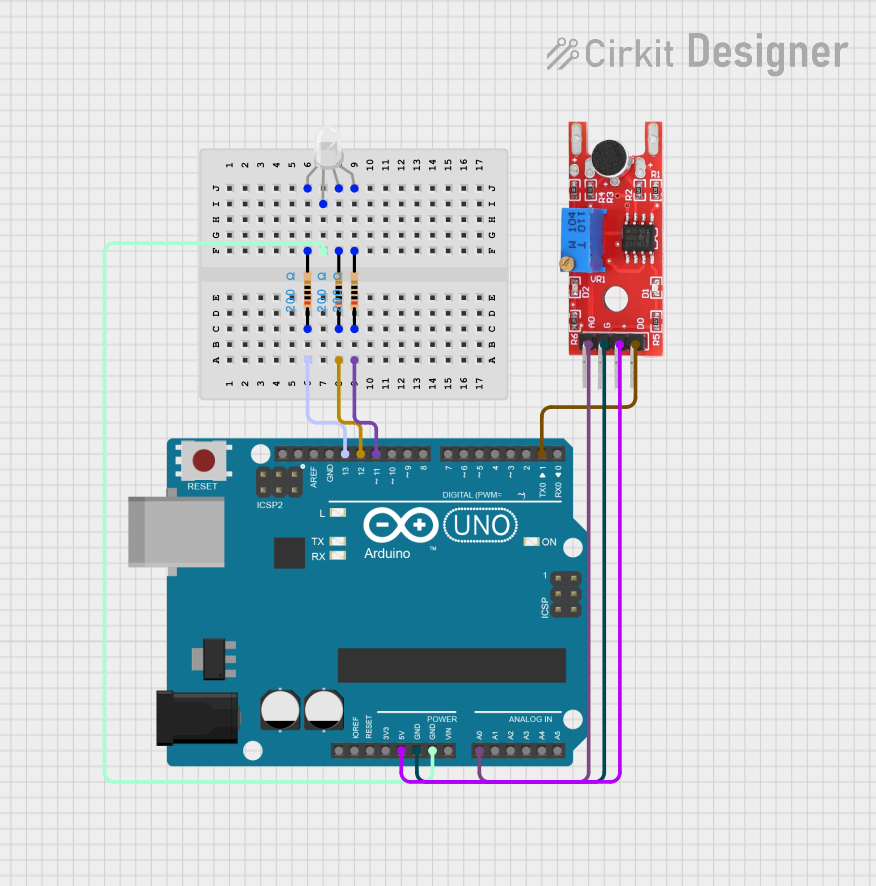
Connecting the KY-016 to a Circuit

  1. Connect the common anode (V+) pin to the positive supply voltage (typically 5V).
  2. Connect each of the R, G, and B pins to a digital output pin on your microcontroller through a current-limiting resistor (typically 220 ohms to 330 ohms).
  3. Ensure that the microcontroller's ground is connected to the negative side of the power supply.

Controlling the KY-016 with an Arduino

To control the KY-016 RGB LED with an Arduino UNO, you can use the following example code:

// Define the RGB LED pins
const int redPin = 11;    // R pin connected to digital pin 11
const int greenPin = 10;  // G pin connected to digital pin 10
const int bluePin = 9;    // B pin connected to digital pin 9

void setup() {
  // Set the RGB LED pins as outputs
  pinMode(redPin, OUTPUT);
  pinMode(greenPin, OUTPUT);
  pinMode(bluePin, OUTPUT);
}

void loop() {
  // Set the color to red
  analogWrite(redPin, 255);   // Red at full intensity
  analogWrite(greenPin, 0);   // Green off
  analogWrite(bluePin, 0);    // Blue off
  delay(1000);                // Wait for 1 second

  // Set the color to green
  analogWrite(redPin, 0);     // Red off
  analogWrite(greenPin, 255); // Green at full intensity
  analogWrite(bluePin, 0);    // Blue off
  delay(1000);                // Wait for 1 second

  // Set the color to blue
  analogWrite(redPin, 0);     // Red off
  analogWrite(greenPin, 0);   // Green off
  analogWrite(bluePin, 255);  // Blue at full intensity
  delay(1000);                // Wait for 1 second
}

Important Considerations and Best Practices

  • Always use current-limiting resistors to prevent damage to the LEDs.
  • Avoid exceeding the peak forward current to ensure the longevity of the module.
  • Use PWM (Pulse Width Modulation) to control the intensity of each LED for creating custom colors.

Troubleshooting and FAQs

Common Issues

  • LEDs are not lighting up: Check the connections and ensure that the current-limiting resistors are in place. Also, verify that the power supply voltage matches the module's requirements.
  • Colors are not as expected: Ensure that the PWM values in the code match the desired color mix. Adjust the values to fine-tune the color output.

Solutions and Tips for Troubleshooting

  • Double-check wiring and solder joints for any loose connections or shorts.
  • Use a multimeter to verify that the appropriate voltage is reaching the RGB LED pins.
  • If using an Arduino, ensure that the correct pins are defined in the code and that they are configured as outputs.

FAQs

Q: Can I use the KY-016 RGB LED module with a 3.3V system? A: Yes, but the brightness may be reduced. Use appropriate current-limiting resistors for 3.3V operation.

Q: How can I create different colors with the KY-016? A: By adjusting the PWM values sent to each color pin, you can mix red, green, and blue to create a wide range of colors.

Q: Is it possible to chain multiple KY-016 modules together? A: Yes, you can connect multiple modules in parallel, ensuring each has its own set of current-limiting resistors.

This documentation provides a comprehensive guide to using the KY-016 RGB LED module in your projects. With proper usage and handling, this module can add vibrant and dynamic lighting effects to your electronic designs.