How to Use muscle signal: Examples, Pinouts, and Specs

Introduction
The Muscle Signal component, manufactured by Arduino, is an advanced sensor designed to detect electrical signals generated by muscle activity. These signals, known as electromyograms (EMGs), are commonly used in biomedical applications to control prosthetics, robotic arms, and other assistive devices. By capturing and interpreting muscle signals, this component enables precise and responsive control of various electronic systems.
Explore Projects Built with muscle signal
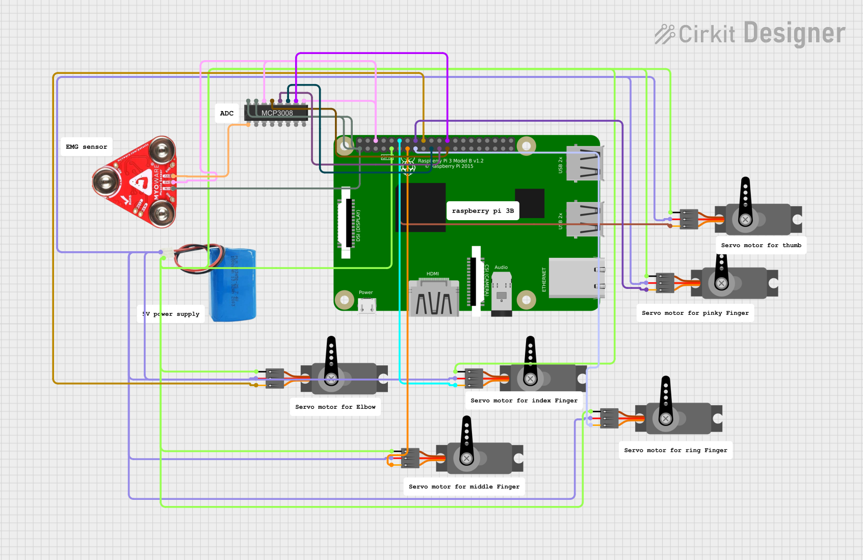
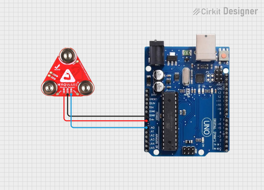
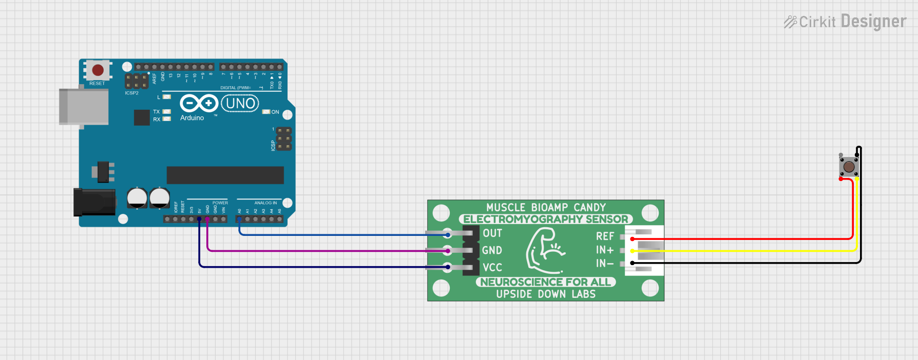
Explore Projects Built with muscle signal
Technical Specifications
Key Technical Details
| Parameter | Value |
|---|---|
| Operating Voltage | 3.3V - 5V |
| Operating Current | 5mA |
| Signal Output | Analog |
| Frequency Range | 20Hz - 500Hz |
| Gain | Adjustable (up to 1000x) |
| Input Impedance | >1MΩ |
| Output Impedance | <1kΩ |
| Dimensions | 25mm x 35mm x 5mm |
Pin Configuration and Descriptions
| Pin Number | Pin Name | Description |
|---|---|---|
| 1 | VCC | Power supply (3.3V - 5V) |
| 2 | GND | Ground |
| 3 | SIG | Analog signal output |
| 4 | REF | Reference voltage (optional, for signal stability) |
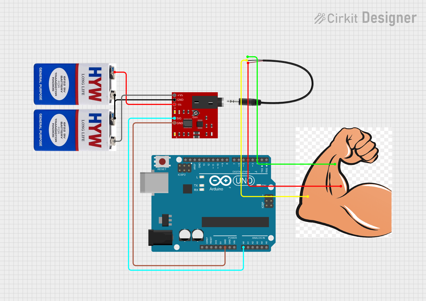
Usage Instructions
How to Use the Component in a Circuit
- Power Supply: Connect the VCC pin to a 3.3V or 5V power supply and the GND pin to the ground of your circuit.
- Signal Output: Connect the SIG pin to an analog input pin on your microcontroller (e.g., Arduino UNO).
- Reference Voltage (Optional): If needed, connect the REF pin to a stable reference voltage to improve signal stability.
Important Considerations and Best Practices
- Electrode Placement: Ensure that the electrodes are placed correctly on the muscle to capture accurate signals. Clean the skin surface before attaching the electrodes to reduce noise.
- Signal Conditioning: Use appropriate filtering and amplification to condition the raw EMG signal for better accuracy and responsiveness.
- Calibration: Calibrate the sensor to account for individual differences in muscle signal strength and noise levels.
- Safety: Avoid placing electrodes near sensitive areas or open wounds. Ensure that the power supply is within the specified range to prevent damage to the component.
Example Code for Arduino UNO
// Muscle Signal Component Example Code
// This code reads the analog signal from the muscle signal component
// and prints the value to the Serial Monitor.

const int muscleSignalPin = A0; // Analog pin connected to SIG pin

void setup() {
  Serial.begin(9600); // Initialize serial communication at 9600 baud
}

void loop() {
  int muscleSignalValue = analogRead(muscleSignalPin); // Read the analog value
  Serial.print("Muscle Signal Value: ");
  Serial.println(muscleSignalValue); // Print the value to the Serial Monitor
  delay(100); // Delay for 100 milliseconds
}
Troubleshooting and FAQs
Common Issues Users Might Face
No Signal Detected:
- Solution: Check the power supply connections and ensure that the electrodes are properly attached to the muscle. Verify that the analog input pin on the microcontroller is correctly connected to the SIG pin.
Noisy Signal:
- Solution: Clean the skin surface before attaching the electrodes. Use shielded cables to reduce electromagnetic interference. Implement software filtering to smooth out the signal.
Weak Signal:
- Solution: Adjust the gain settings to amplify the signal. Ensure that the electrodes are placed on the muscle belly for optimal signal strength.
FAQs
Q1: Can I use the muscle signal component with other microcontrollers besides Arduino UNO?
- A1: Yes, the muscle signal component can be used with any microcontroller that has an analog input pin and supports the operating voltage range.
Q2: How do I adjust the gain of the muscle signal component?
- A2: The gain can be adjusted using the onboard potentiometer. Turn the potentiometer clockwise to increase the gain and counterclockwise to decrease it.
Q3: What type of electrodes should I use with the muscle signal component?
- A3: Use disposable adhesive electrodes designed for EMG applications. Ensure that the electrodes have good conductivity and are properly attached to the skin.
Q4: Can I use the muscle signal component for long-term monitoring?
- A4: Yes, but ensure that the electrodes are periodically checked and replaced as needed. Also, monitor the power supply to prevent any interruptions.
By following this documentation, users can effectively integrate the muscle signal component into their projects, ensuring accurate and reliable muscle signal detection for various applications.