How to Use Micro:bit Breakout: Examples, Pinouts, and Specs
Introduction
The Micro:bit Breakout is a versatile breakout board designed to expand the functionality of the BBC Micro:bit microcontroller. It provides easy access to the Micro:bit's GPIO pins, power supply, and additional features such as sensors and connectors, making it an ideal tool for prototyping, experimentation, and educational projects. By using the Micro:bit Breakout, users can seamlessly connect external components like LEDs, motors, sensors, and more, enabling a wide range of creative applications.
Explore Projects Built with Micro:bit Breakout
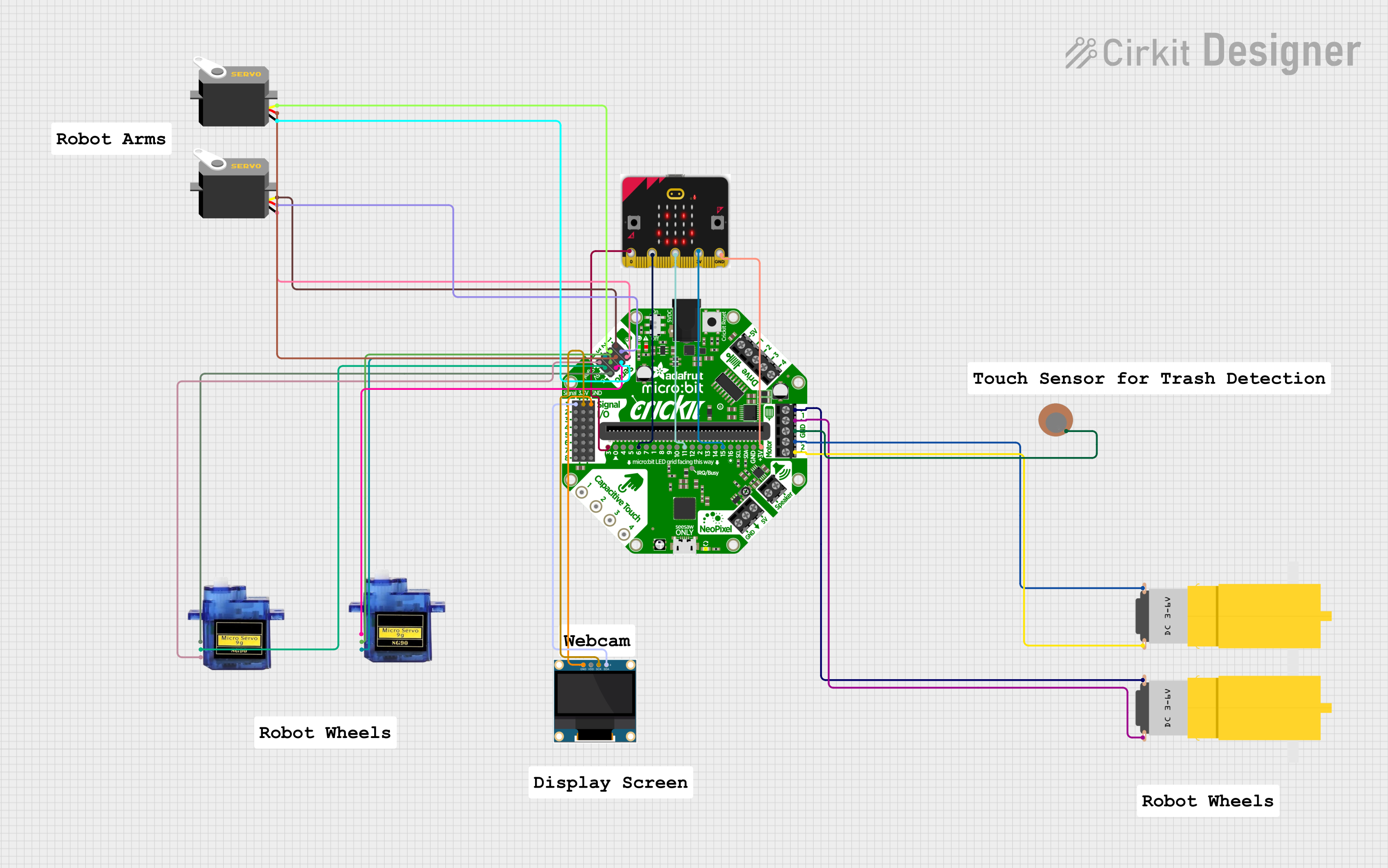
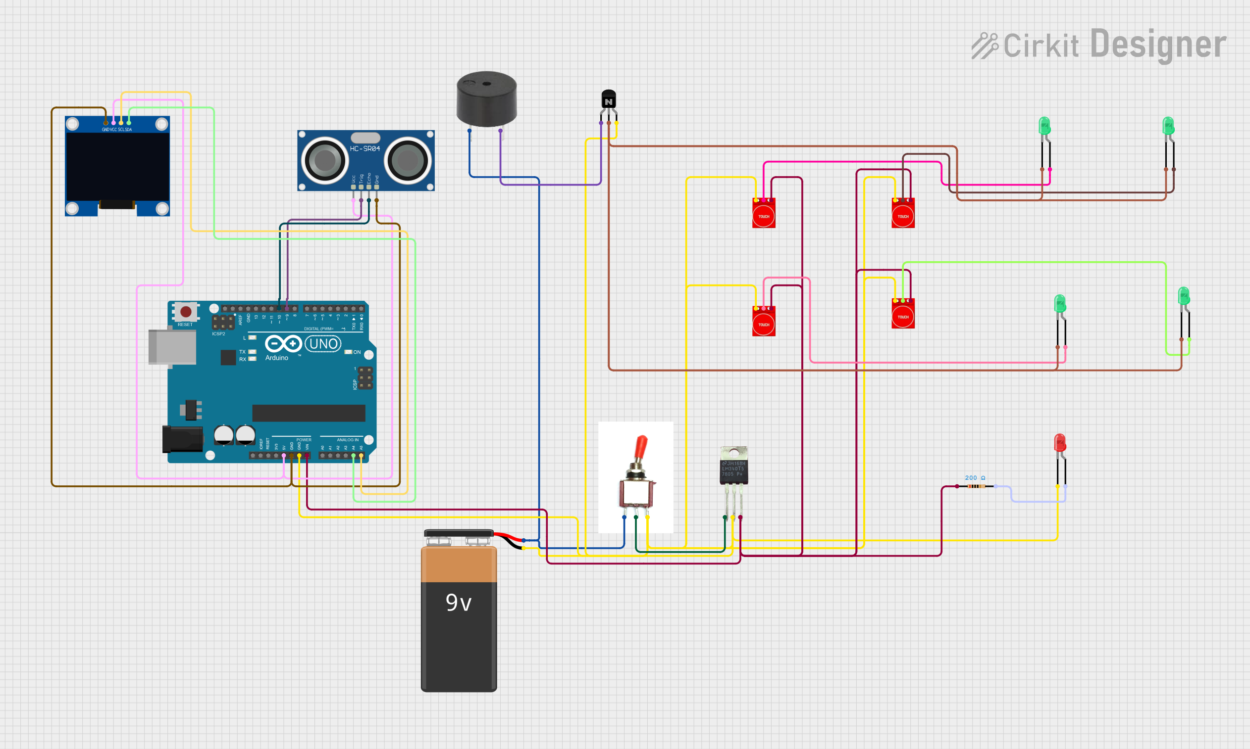


Explore Projects Built with Micro:bit Breakout
Common Applications and Use Cases
- Educational projects for learning electronics and programming
- Prototyping circuits and testing hardware designs
- Connecting external sensors, actuators, and modules
- Building interactive devices and IoT projects
- Robotics and automation systems
Technical Specifications
The Micro:bit Breakout is designed to interface with the BBC Micro:bit and provides the following technical features:
Key Technical Details
- Input Voltage: 3.3V to 5V (via Micro:bit or external power supply)
- GPIO Access: Breakout for all 21 GPIO pins of the Micro:bit
- Power Supply: 3.3V and GND rails for external components
- Additional Features:
- Dedicated connectors for I2C and SPI communication
- Onboard reset button for the Micro:bit
- Screw terminals for secure connections
- Edge connector for easy Micro:bit insertion
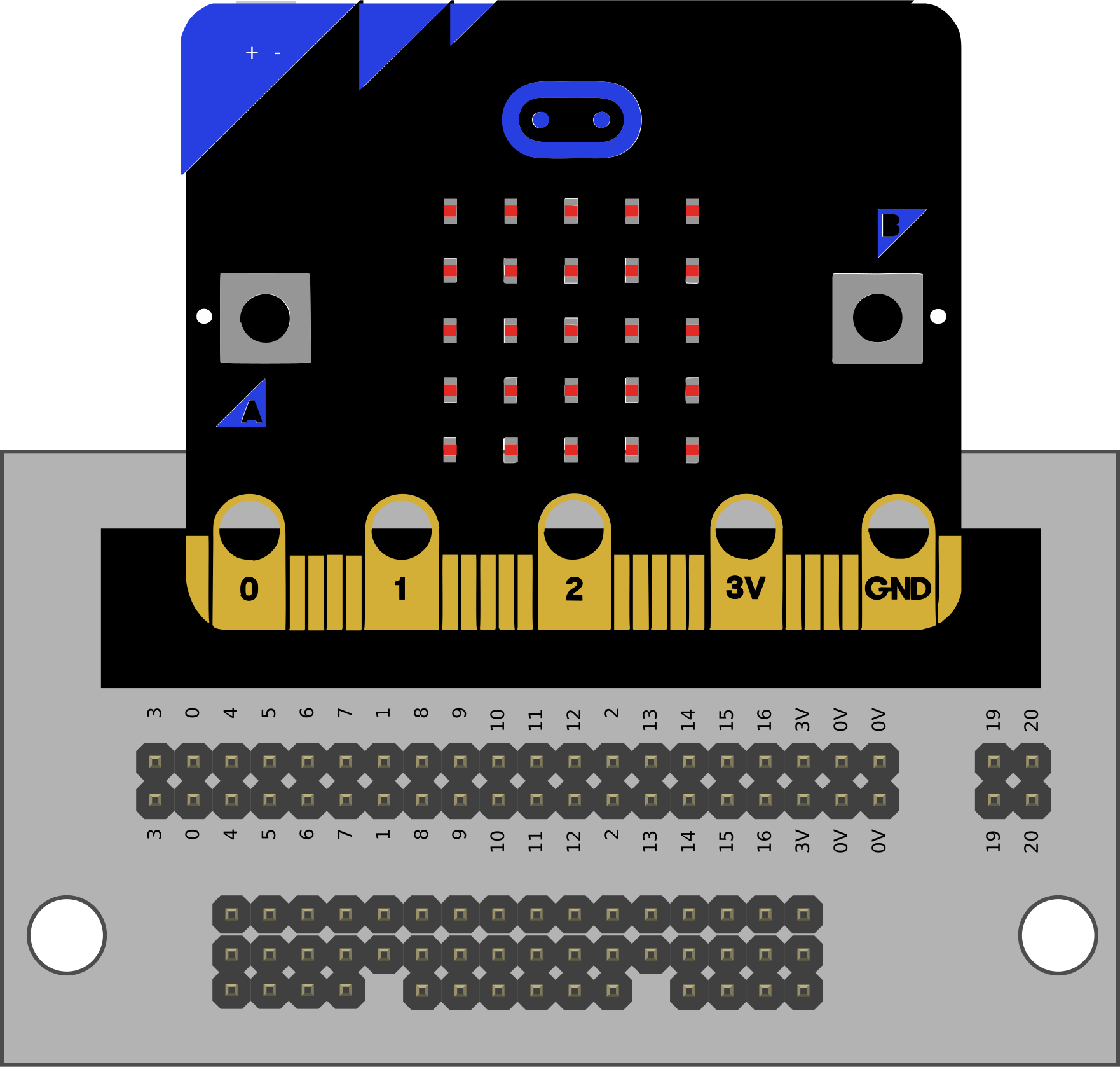
Pin Configuration and Descriptions
The Micro:bit Breakout provides access to the Micro:bit's GPIO pins through labeled headers. Below is a table describing the pin configuration:
| Pin Name | Micro:bit Pin | Description |
|---|---|---|
| P0 | Pin 0 | General-purpose I/O, analog input |
| P1 | Pin 1 | General-purpose I/O, analog input |
| P2 | Pin 2 | General-purpose I/O, analog input |
| P3 | Pin 3 | Analog input (shared with microphone) |
| P4 | Pin 4 | General-purpose I/O, analog input |
| P5 | Pin 5 | Button A input |
| P6-P8 | Pins 6-8 | General-purpose I/O |
| P9 | Pin 9 | Button B input |
| P10 | Pin 10 | General-purpose I/O, analog input |
| P11-P20 | Pins 11-20 | General-purpose I/O, I2C, SPI |
| 3V3 | - | 3.3V power supply |
| GND | - | Ground |
Usage Instructions
How to Use the Micro:bit Breakout in a Circuit
- Insert the Micro:bit: Slide the BBC Micro:bit into the edge connector of the breakout board, ensuring proper alignment.
- Connect External Components: Use the labeled GPIO headers or screw terminals to connect external components like LEDs, sensors, or motors.
- Power the Breakout Board: Supply power to the breakout board either through the Micro:bit's USB port or an external power source (3.3V to 5V).
- Write and Upload Code: Program the Micro:bit using the MakeCode editor, Python, or other supported environments. Upload the code to the Micro:bit via USB.
Important Considerations and Best Practices
- Voltage Levels: Ensure that external components are compatible with the Micro:bit's 3.3V logic level.
- Avoid Overloading Pins: Do not exceed the maximum current rating of 5mA per GPIO pin.
- Secure Connections: Use screw terminals for a more reliable connection when working with motors or other high-current devices.
- I2C and SPI Devices: Use the dedicated I2C and SPI connectors for easier communication with compatible modules.
Example Code for Arduino-like Functionality
The following example demonstrates how to blink an LED connected to pin P0 of the Micro:bit Breakout:
Import the Micro:bit module for GPIO control
from microbit import *
Set up the LED pin (P0) as an output
led_pin = pin0
while True: led_pin.write_digital(1) # Turn the LED on sleep(1000) # Wait for 1 second led_pin.write_digital(0) # Turn the LED off sleep(1000) # Wait for 1 second
Troubleshooting and FAQs
Common Issues and Solutions
Micro:bit Not Powering On:
- Cause: Improper power supply or loose connection.
- Solution: Ensure the Micro:bit is securely inserted into the edge connector and verify the power source.
External Components Not Working:
- Cause: Incorrect wiring or incompatible voltage levels.
- Solution: Double-check the wiring and ensure components are compatible with 3.3V logic.
I2C/SPI Devices Not Communicating:
- Cause: Incorrect pin connections or address conflicts.
- Solution: Verify the connections to the dedicated I2C/SPI headers and check for address conflicts in the code.
GPIO Pins Not Responding:
- Cause: Exceeding current limits or incorrect pin configuration.
- Solution: Ensure the current draw is within limits and verify the pin mode in the code.
FAQs
Q: Can I use 5V components with the Micro:bit Breakout?
A: The Micro:bit operates at 3.3V logic levels. While some 5V components may work, it is recommended to use level shifters for proper operation.
Q: How do I connect multiple sensors to the breakout board?
A: Use the I2C or SPI connectors for multiple sensors. Ensure each device has a unique address or uses separate chip select pins.
Q: Is the breakout board compatible with all versions of the Micro:bit?
A: Yes, the breakout board is compatible with both Micro:bit V1 and V2.
Q: Can I power motors directly from the breakout board?
A: No, motors typically require more current than the Micro:bit can supply. Use an external motor driver or power supply.