How to Use Module Sim a7680c: Examples, Pinouts, and Specs
Introduction
The Module Sim a7680c is a simulation module developed by Arduino, designed to facilitate the testing and analysis of electronic circuits. This versatile module provides a platform for simulating various circuit configurations and behaviors, enabling engineers and hobbyists to optimize their designs before physical implementation. By offering a reliable and efficient way to model circuit performance, the Module Sim a7680c reduces development time and minimizes the risk of errors in final designs.
Explore Projects Built with Module Sim a7680c

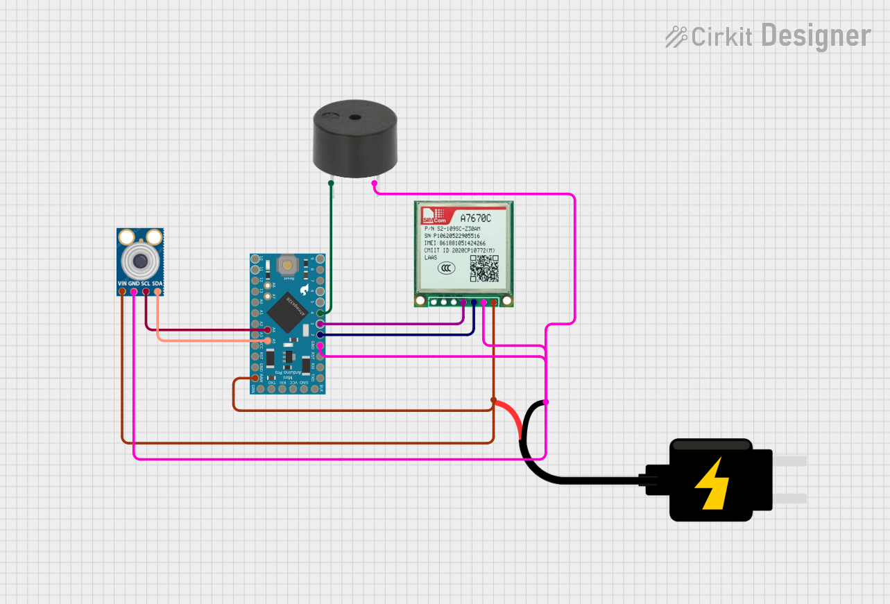

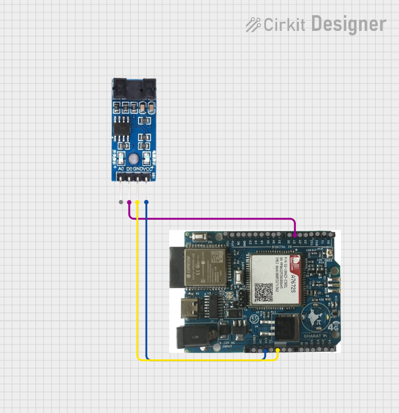
Explore Projects Built with Module Sim a7680c
Common Applications and Use Cases
- Circuit Design and Testing: Simulate and analyze circuit behavior before building physical prototypes.
- Educational Purposes: Teach and learn circuit design principles in academic settings.
- Optimization: Fine-tune circuit parameters for improved performance.
- Debugging: Identify and resolve potential issues in circuit designs.
- Prototyping: Test new ideas and configurations without the need for physical components.
Technical Specifications
The Module Sim a7680c is equipped with advanced features to support a wide range of simulation tasks. Below are its key technical details:
General Specifications
| Parameter | Value |
|---|---|
| Manufacturer | Arduino |
| Operating Voltage | 3.3V to 5V |
| Power Consumption | 50mA (typical) |
| Communication Interface | UART, SPI, I2C |
| Simulation Modes | Analog, Digital, Mixed-Signal |
| Operating Temperature | -20°C to 70°C |
| Dimensions | 50mm x 30mm x 10mm |
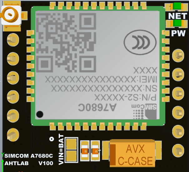
Pin Configuration and Descriptions
The Module Sim a7680c features a standard pinout for easy integration into various setups. Below is the pin configuration:
| Pin Number | Pin Name | Description |
|---|---|---|
| 1 | VCC | Power supply input (3.3V to 5V) |
| 2 | GND | Ground connection |
| 3 | TX | UART Transmit pin |
| 4 | RX | UART Receive pin |
| 5 | SCL | I2C Clock line |
| 6 | SDA | I2C Data line |
| 7 | CS | SPI Chip Select |
| 8 | MOSI | SPI Master Out Slave In |
| 9 | MISO | SPI Master In Slave Out |
| 10 | SCK | SPI Clock |
| 11 | ANALOG_IN | Analog input for simulation |
| 12 | DIGITAL_IO | Digital input/output for simulation |
Usage Instructions
The Module Sim a7680c is designed for ease of use in a variety of simulation scenarios. Follow the steps below to integrate and use the module effectively:
Step 1: Powering the Module
- Connect the VCC pin to a 3.3V or 5V power source.
- Connect the GND pin to the ground of your circuit.
Step 2: Communication Setup
- For UART communication, connect the TX and RX pins to the corresponding pins on your microcontroller.
- For I2C communication, connect the SCL and SDA pins to the I2C bus.
- For SPI communication, connect the CS, MOSI, MISO, and SCK pins to the SPI bus.
Step 3: Simulation Configuration
- Use the ANALOG_IN pin to input analog signals for simulation.
- Use the DIGITAL_IO pin for digital signal simulation or control.
Step 4: Programming with Arduino UNO
The Module Sim a7680c can be easily programmed using an Arduino UNO. Below is an example code snippet to simulate a simple analog signal:
// Include necessary libraries
#include <Wire.h>  // For I2C communication
#include <SPI.h>   // For SPI communication

// Define pin connections
#define ANALOG_IN A0  // Analog input pin
#define DIGITAL_IO 7  // Digital I/O pin

void setup() {
  // Initialize serial communication for debugging
  Serial.begin(9600);

  // Configure pins
  pinMode(ANALOG_IN, INPUT);  // Set analog pin as input
  pinMode(DIGITAL_IO, OUTPUT); // Set digital pin as output

  // Print initialization message
  Serial.println("Module Sim a7680c Initialized");
}

void loop() {
  // Read analog value from the input pin
  int analogValue = analogRead(ANALOG_IN);

  // Print the analog value to the serial monitor
  Serial.print("Analog Value: ");
  Serial.println(analogValue);

  // Simulate a digital output based on the analog value
  if (analogValue > 512) {
    digitalWrite(DIGITAL_IO, HIGH);  // Set digital pin HIGH
  } else {
    digitalWrite(DIGITAL_IO, LOW);   // Set digital pin LOW
  }

  // Add a small delay for stability
  delay(100);
}
Important Considerations and Best Practices
- Ensure the power supply voltage matches the module's operating range (3.3V to 5V).
- Avoid connecting multiple communication interfaces (UART, I2C, SPI) simultaneously to prevent conflicts.
- Use proper decoupling capacitors near the power pins to reduce noise.
- Handle the module carefully to avoid damage from electrostatic discharge (ESD).
Troubleshooting and FAQs
Common Issues and Solutions
Module Not Powering On
- Ensure the VCC and GND pins are properly connected.
- Verify the power supply voltage is within the 3.3V to 5V range.
No Communication with Microcontroller
- Check the wiring of the communication interface (UART, I2C, or SPI).
- Ensure the correct baud rate or communication settings are configured in your code.
Incorrect Simulation Results
- Verify the input signals are within the module's supported range.
- Check for loose or incorrect connections.
Overheating
- Ensure the module is not drawing excessive current.
- Verify the operating temperature is within the specified range (-20°C to 70°C).
FAQs
Q1: Can the Module Sim a7680c simulate both analog and digital circuits?
A1: Yes, the module supports analog, digital, and mixed-signal simulations.
Q2: Is the module compatible with other microcontrollers besides Arduino?
A2: Yes, the module can be used with any microcontroller that supports UART, I2C, or SPI communication.
Q3: What is the maximum sampling rate for analog signals?
A3: The maximum sampling rate depends on the microcontroller and communication interface used. Refer to the Arduino documentation for specific details.
Q4: Can I use the module for real-time circuit emulation?
A4: The module is designed for simulation purposes and may not support real-time emulation for high-speed circuits.
By following this documentation, users can effectively utilize the Module Sim a7680c for a wide range of simulation tasks, ensuring accurate and reliable results.