How to Use Manifold Pressure Sensor: Examples, Pinouts, and Specs
Introduction
The Manifold Pressure Sensor is a device designed to measure the pressure of the air or fuel mixture within the intake manifold of an engine. This critical data is used by engine control units (ECUs) to optimize fuel injection, ignition timing, and overall engine performance. By providing real-time pressure readings, the sensor ensures efficient engine operation, reduced emissions, and improved fuel economy.
Explore Projects Built with Manifold Pressure Sensor
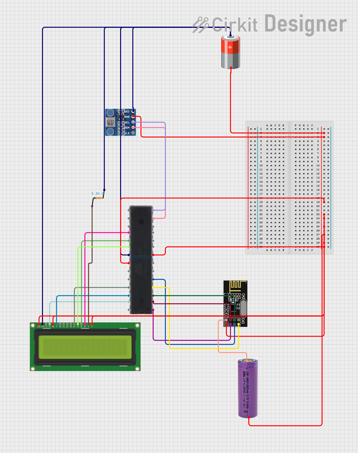
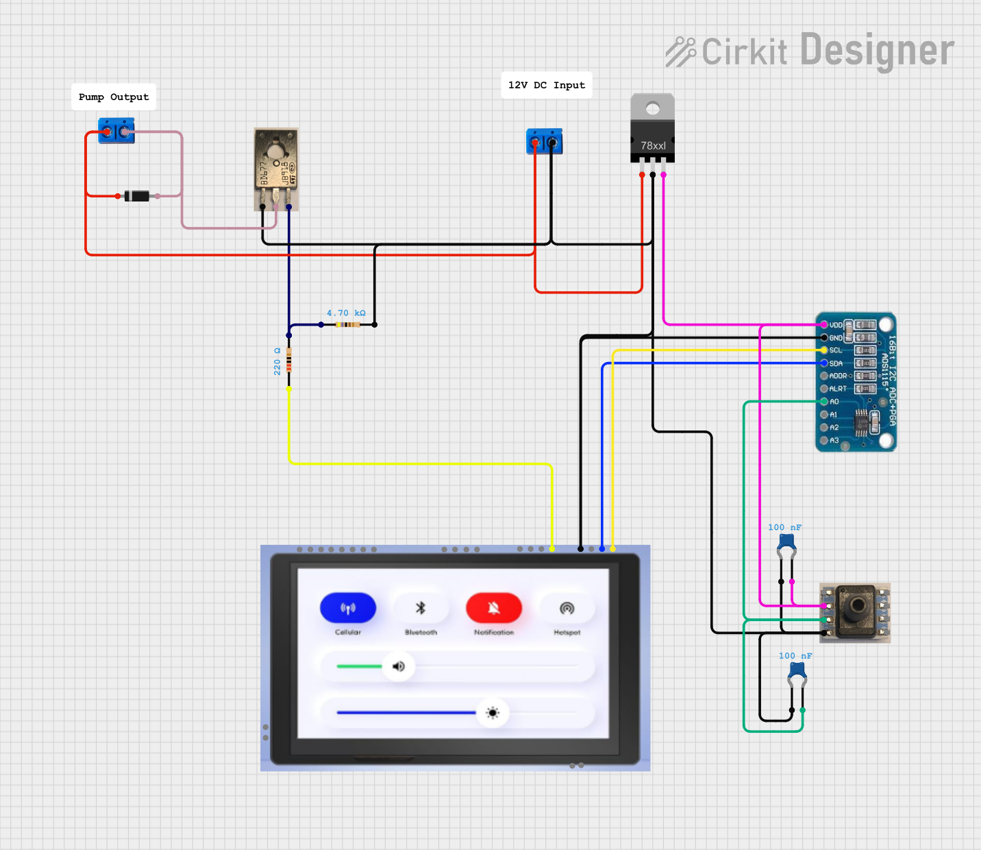
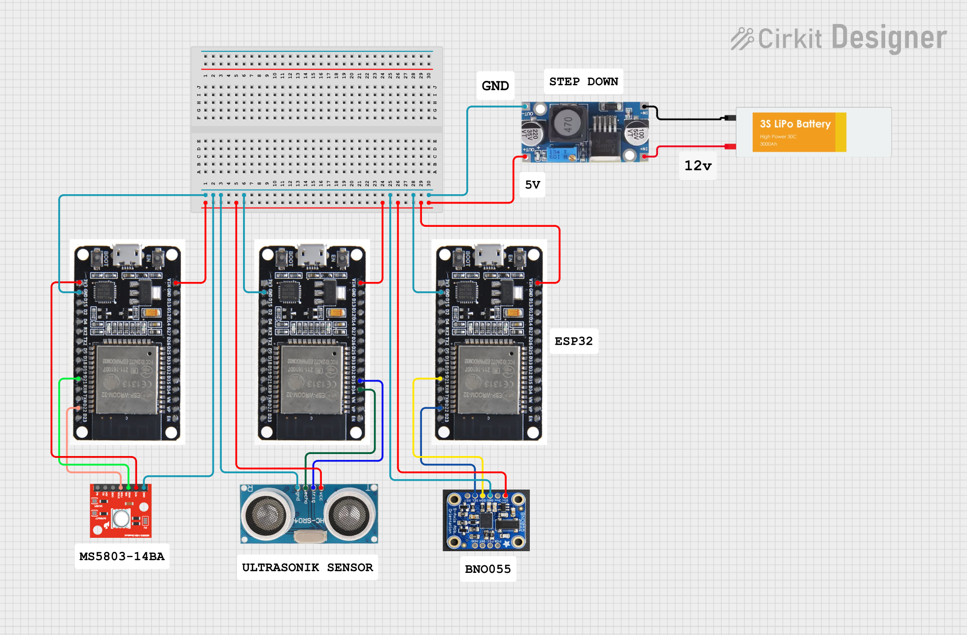
Explore Projects Built with Manifold Pressure Sensor
Common Applications and Use Cases
- Automotive engine management systems
- Turbocharged and supercharged engines
- Fuel injection systems
- Diagnostic tools for engine performance monitoring
- Industrial engines and generators
Technical Specifications
Below are the key technical details for the Manifold Pressure Sensor:
| Parameter | Value |
|---|---|
| Manufacturer | Manifold Pressure |
| Part ID | Manifold Pressure Sensor |
| Operating Voltage | 5V DC |
| Output Signal | Analog voltage (0.5V to 4.5V) |
| Pressure Range | 20 kPa to 250 kPa (absolute) |
| Accuracy | ±1.5% of full scale |
| Operating Temperature | -40°C to +125°C |
| Response Time | < 1 ms |
| Connector Type | 3-pin (VCC, GND, Signal) |
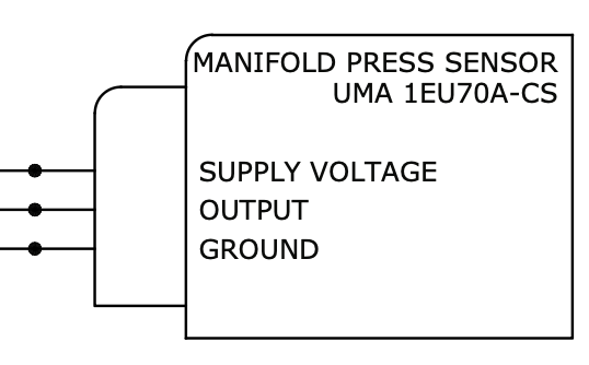
Pin Configuration and Descriptions
The Manifold Pressure Sensor has a 3-pin connector. The pinout is as follows:
| Pin | Name | Description |
|---|---|---|
| 1 | VCC | Power supply input (5V DC) |
| 2 | GND | Ground connection |
| 3 | Signal | Analog output signal proportional to manifold pressure |
Usage Instructions
How to Use the Component in a Circuit
- Power Supply: Connect the VCC pin to a regulated 5V DC power source. Ensure the power supply is stable to avoid inaccurate readings.
- Ground Connection: Connect the GND pin to the ground of your circuit.
- Signal Output: Connect the Signal pin to an analog input pin of a microcontroller or data acquisition system.
- Calibration: Some systems may require calibration to interpret the sensor's output correctly. Refer to your ECU or microcontroller documentation for calibration procedures.
Important Considerations and Best Practices
- Avoid Overvoltage: Do not exceed the 5V operating voltage, as this may damage the sensor.
- Placement: Install the sensor close to the intake manifold to ensure accurate pressure readings.
- Wiring: Use shielded cables for the Signal pin to minimize noise interference.
- Temperature: Ensure the sensor operates within its specified temperature range (-40°C to +125°C).
- Sealing: Properly seal the sensor to prevent contamination from dust, oil, or moisture.
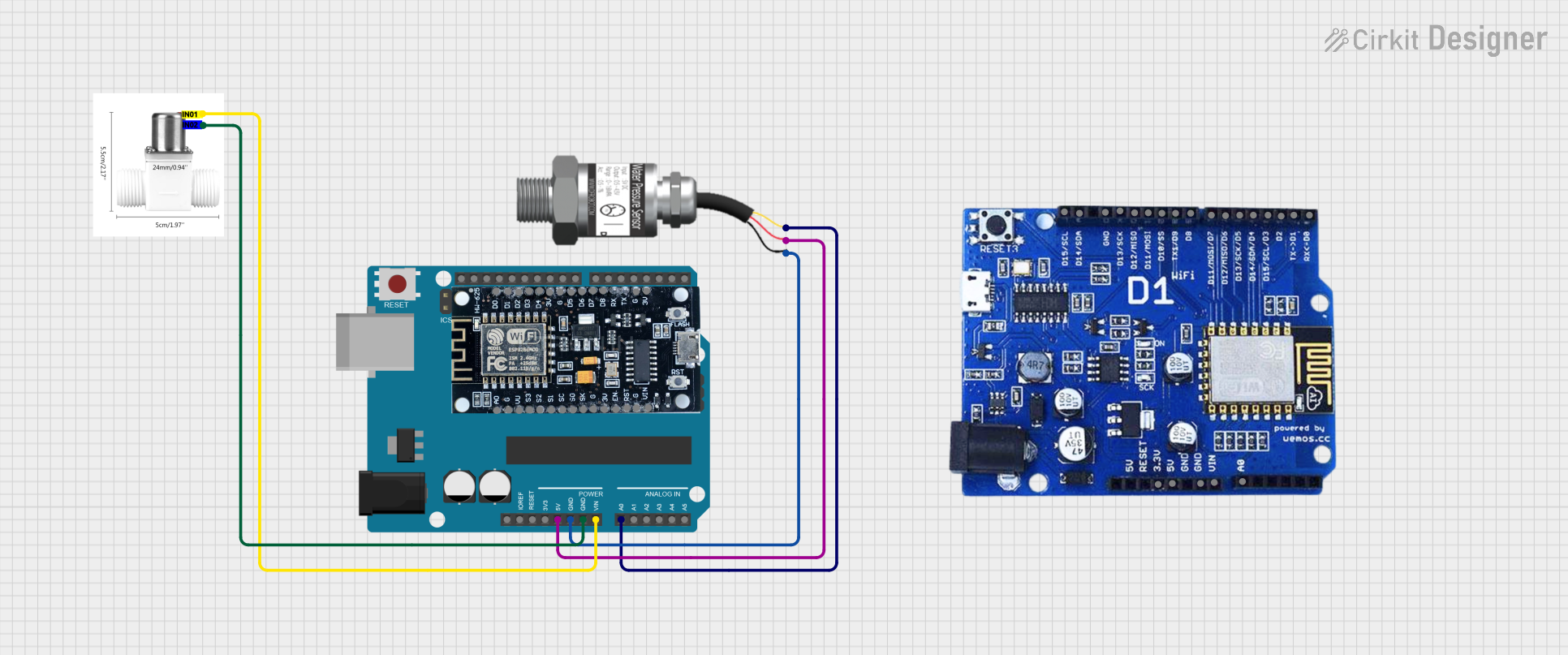
Example: Connecting to an Arduino UNO
Below is an example of how to connect the Manifold Pressure Sensor to an Arduino UNO and read its output:
Circuit Diagram
- VCC: Connect to the Arduino's 5V pin.
- GND: Connect to the Arduino's GND pin.
- Signal: Connect to the Arduino's analog input pin (e.g., A0).
Arduino Code
// Manifold Pressure Sensor Example Code
// Reads the analog output of the sensor and converts it to pressure in kPa.

const int sensorPin = A0; // Analog pin connected to the sensor's Signal pin
const float voltageRef = 5.0; // Reference voltage of the Arduino (5V)
const float minVoltage = 0.5; // Minimum sensor output voltage (0.5V)
const float maxVoltage = 4.5; // Maximum sensor output voltage (4.5V)
const float minPressure = 20.0; // Minimum pressure in kPa
const float maxPressure = 250.0; // Maximum pressure in kPa

void setup() {
  Serial.begin(9600); // Initialize serial communication
}

void loop() {
  int sensorValue = analogRead(sensorPin); // Read the analog value (0-1023)
  float voltage = (sensorValue / 1023.0) * voltageRef; // Convert to voltage
  float pressure = ((voltage - minVoltage) / (maxVoltage - minVoltage)) *
                   (maxPressure - minPressure) + minPressure;
  // Map voltage to pressure range

  Serial.print("Pressure: ");
  Serial.print(pressure);
  Serial.println(" kPa");

  delay(500); // Wait 500ms before the next reading
}
Troubleshooting and FAQs
Common Issues and Solutions
No Output Signal:
- Cause: Incorrect wiring or no power supply.
- Solution: Verify all connections and ensure the sensor is powered with 5V DC.
Inaccurate Readings:
- Cause: Electrical noise or improper calibration.
- Solution: Use shielded cables for the Signal pin and recalibrate the system.
Sensor Overheating:
- Cause: Operating outside the specified temperature range.
- Solution: Ensure the sensor is installed in a location with proper thermal management.
Fluctuating Output:
- Cause: Unstable power supply or loose connections.
- Solution: Use a stable power source and check all connections.
FAQs
Q: Can this sensor be used with a 3.3V microcontroller?
A: No, the sensor requires a 5V power supply for proper operation. However, you can use a voltage divider or level shifter to interface the Signal pin with a 3.3V microcontroller.
Q: How do I clean the sensor?
A: Use a soft, dry cloth to clean the sensor. Avoid using water or solvents, as they may damage the internal components.
Q: What happens if the sensor is exposed to pressures outside its range?
A: Exceeding the pressure range may result in permanent damage to the sensor or inaccurate readings. Always ensure the sensor is used within its specified range (20 kPa to 250 kPa).