How to Use 12 High pressure pump: Examples, Pinouts, and Specs
12V High-Pressure Pump Documentation
1. Introduction
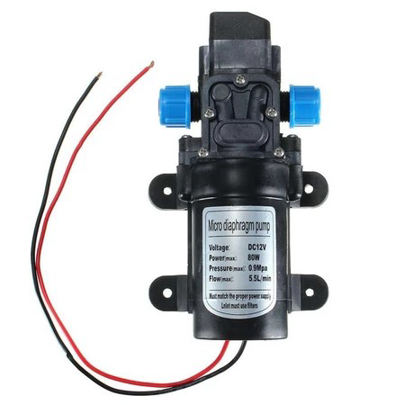
The 12V High-Pressure Pump is a versatile and robust fluid transfer device designed to operate at elevated pressures. It is commonly used in industrial, agricultural, and domestic applications where high-pressure fluid movement is required. This pump is powered by a 12V DC power source, making it compatible with a wide range of systems, including automotive, solar-powered setups, and microcontroller-based projects.
Common Applications:
- Industrial Cleaning: High-pressure water jets for cleaning machinery and surfaces.
- Agriculture: Spraying pesticides, herbicides, or fertilizers.
- Fluid Transfer: Moving liquids such as water, oil, or chemicals between containers.
- DIY Projects: Integration with Arduino or other microcontrollers for automated fluid control.
- Cooling Systems: Circulating coolant in closed-loop systems.
2. Technical Specifications
The following table outlines the key technical details of the 12V High-Pressure Pump:
| Parameter | Value |
|---|---|
| Operating Voltage | 12V DC |
| Operating Current | 3A (typical), 5A (maximum) |
| Maximum Pressure | 100 PSI (6.9 bar) |
| Flow Rate | 4.5 L/min (1.2 GPM) |
| Inlet/Outlet Diameter | 10 mm (3/8 inch) |
| Pump Type | Diaphragm |
| Duty Cycle | 30 minutes (continuous use) |
| Weight | 1.2 kg |
| Dimensions | 180 mm x 100 mm x 60 mm |
| Noise Level | ≤ 65 dB |
Pin Configuration and Descriptions
The pump typically has two electrical connections for power input. The table below describes these connections:
| Pin/Connection | Description |
|---|---|
| Positive (+) | Connect to the positive terminal of a 12V DC power source. |
| Negative (-) | Connect to the negative terminal (ground) of the power source. |
3. Usage Instructions
Connecting the Pump to a Circuit
- Power Supply: Ensure you have a stable 12V DC power source capable of supplying at least 5A.
- Polarity: Connect the positive (+) terminal of the pump to the positive terminal of the power source and the negative (-) terminal to the ground.
- Fluid Connections: Attach hoses to the inlet and outlet ports of the pump. Ensure the connections are secure to prevent leaks.
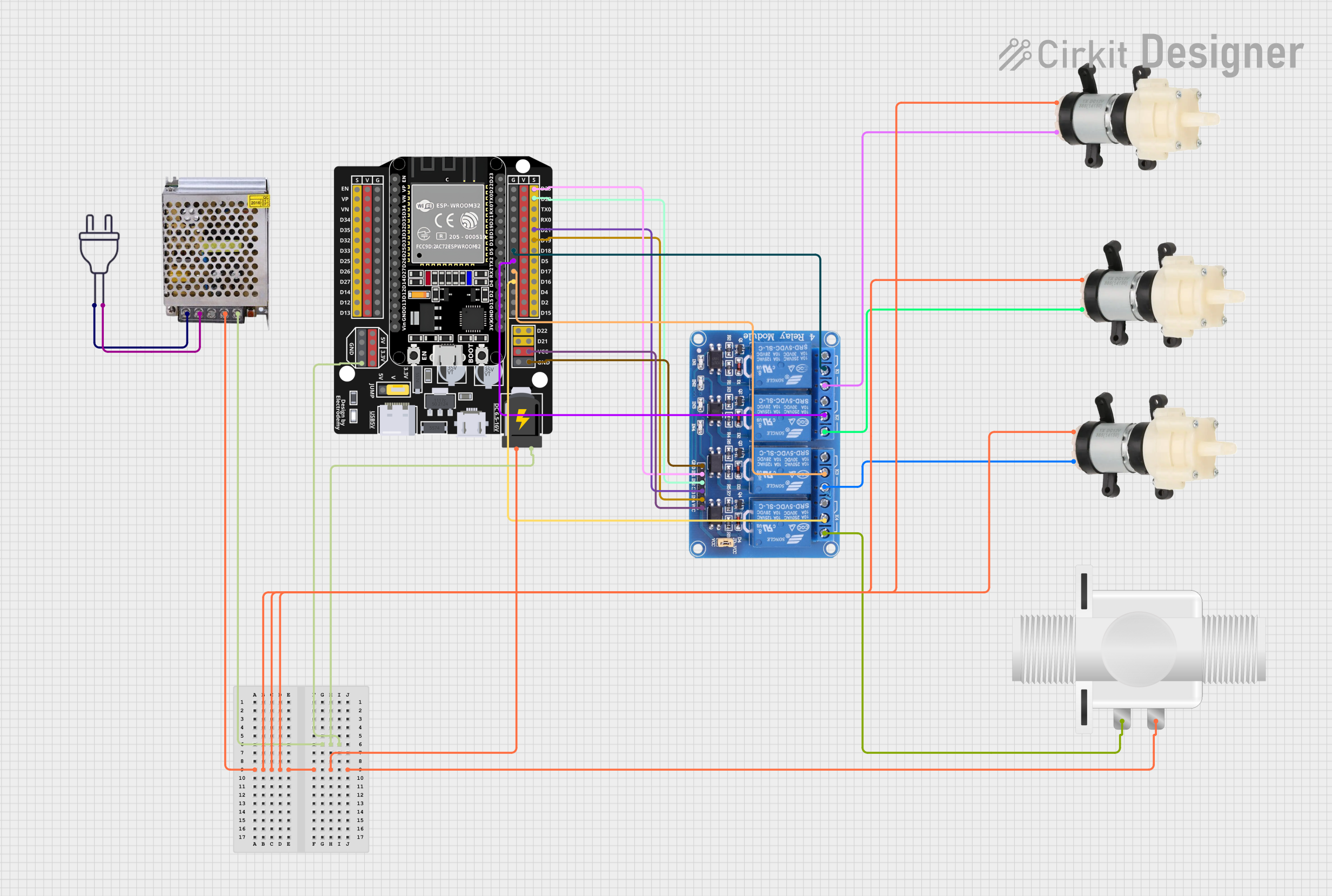
- Control (Optional): For automated control, you can use a relay module or a motor driver to switch the pump on and off using a microcontroller like an Arduino.
Important Considerations:
- Priming: Ensure the pump is primed (filled with fluid) before operation to avoid damage.
- Duty Cycle: Do not exceed the recommended duty cycle of 30 minutes to prevent overheating.
- Filtration: Use a filter on the inlet side to prevent debris from entering the pump.
- Mounting: Secure the pump to a stable surface to minimize vibration and noise.
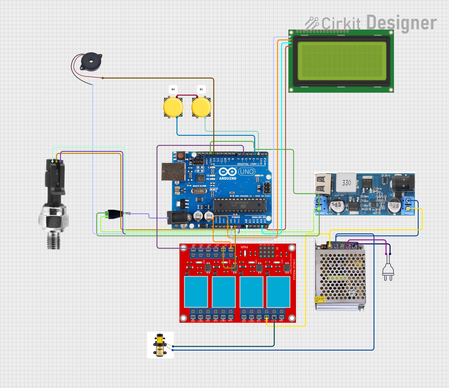
4. Example Arduino Integration
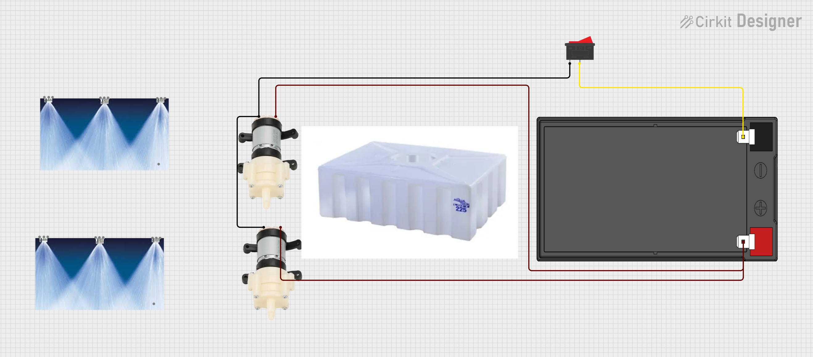
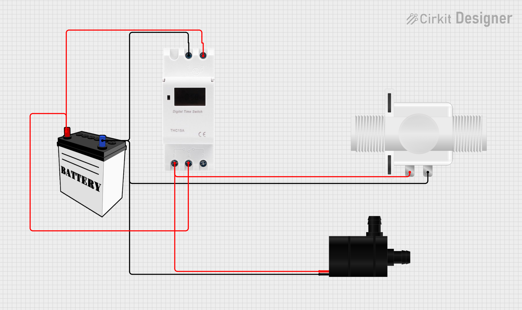
The 12V High-Pressure Pump can be controlled using an Arduino UNO and a relay module. Below is an example circuit and code to toggle the pump on and off using a push button.
Circuit Diagram:
- Connect the pump's positive terminal to the relay's NO (Normally Open) terminal.
- Connect the relay's COM (Common) terminal to the 12V power supply's positive terminal.
- Connect the pump's negative terminal to the 12V power supply's ground.
- Connect the relay module's control pin to Arduino pin 7.
- Connect a push button to Arduino pin 2 with a pull-down resistor.
Arduino Code:
// Define pin numbers
const int pumpRelayPin = 7; // Relay control pin connected to the pump
const int buttonPin = 2;    // Push button pin

// Variable to store the pump state
bool pumpState = false;

void setup() {
  pinMode(pumpRelayPin, OUTPUT); // Set relay pin as output
  pinMode(buttonPin, INPUT_PULLUP); // Set button pin as input with pull-up
  digitalWrite(pumpRelayPin, LOW); // Ensure pump is off at startup
}

void loop() {
  // Check if the button is pressed
  if (digitalRead(buttonPin) == LOW) {
    delay(200); // Debounce delay
    pumpState = !pumpState; // Toggle pump state
    digitalWrite(pumpRelayPin, pumpState ? HIGH : LOW); // Control relay
  }
}
Notes:
- Use a flyback diode across the relay coil to protect the circuit from voltage spikes.
- Ensure the relay module can handle the pump's current (5A max).
5. Troubleshooting and FAQs
Common Issues and Solutions:
| Issue | Possible Cause | Solution |
|---|---|---|
| Pump does not start | Incorrect wiring or insufficient power | Check connections and power supply. |
| Pump runs but no fluid is pumped | Airlock or dry operation | Prime the pump before use. |
| Overheating | Exceeding duty cycle | Allow the pump to cool after 30 mins. |
| Low pressure or flow rate | Clogged inlet or outlet | Clean the hoses and filter. |
| Excessive noise or vibration | Loose mounting or worn components | Secure the pump and inspect for wear. |
FAQs:
Can I use the pump with a 24V power supply?
No, the pump is designed for 12V DC operation. Using a higher voltage may damage the pump.Is the pump suitable for pumping chemicals?
The pump can handle certain chemicals, but compatibility depends on the material of the diaphragm. Check the manufacturer's specifications for chemical resistance.Can I run the pump continuously?
No, the pump has a duty cycle of 30 minutes. Allow it to cool before resuming operation.How do I reduce noise during operation?
Mount the pump on a vibration-dampening surface and ensure all connections are secure.
This documentation provides a comprehensive guide to using the 12V High-Pressure Pump effectively. For further assistance, refer to the manufacturer's datasheet or contact technical support.
Explore Projects Built with 12 High pressure pump
Explore Projects Built with 12 High pressure pump