How to Use Solar Panel Regulator 5A MPPT Controller Battery Charging 9V/12V/24V/Auto Switch: Examples, Pinouts, and Specs
Introduction
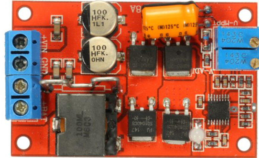
The Solar Panel Regulator 5A MPPT (Maximum Power Point Tracking) Controller is a device designed to optimize the power output from solar panels. By dynamically adjusting the electrical operating point of the solar modules, it ensures efficient energy transfer to charge batteries at various voltage levels (9V, 12V, 24V). The controller features an automatic voltage switching mechanism, making it versatile for a wide range of solar energy systems.
Explore Projects Built with Solar Panel Regulator 5A MPPT Controller Battery Charging 9V/12V/24V/Auto Switch
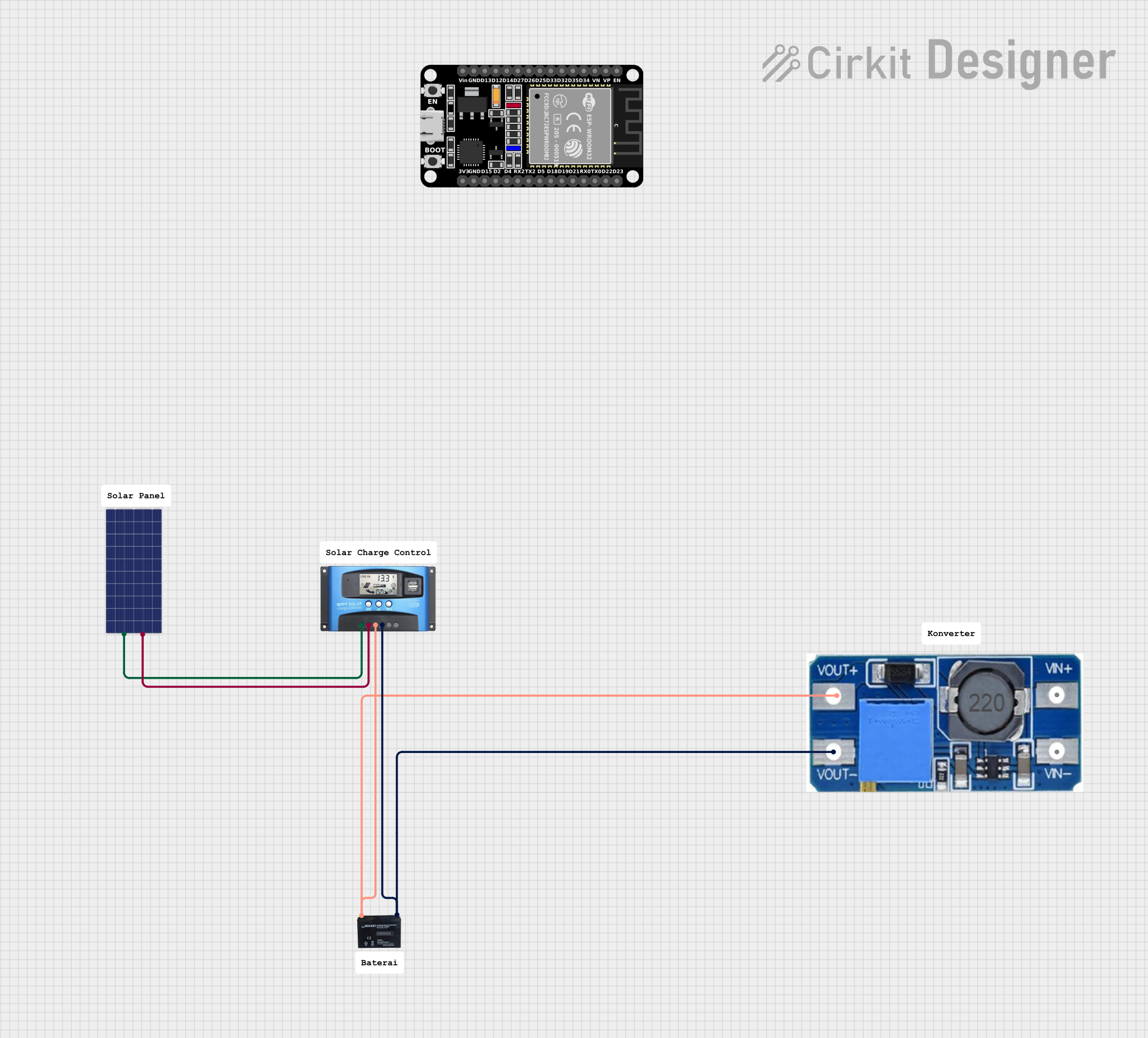
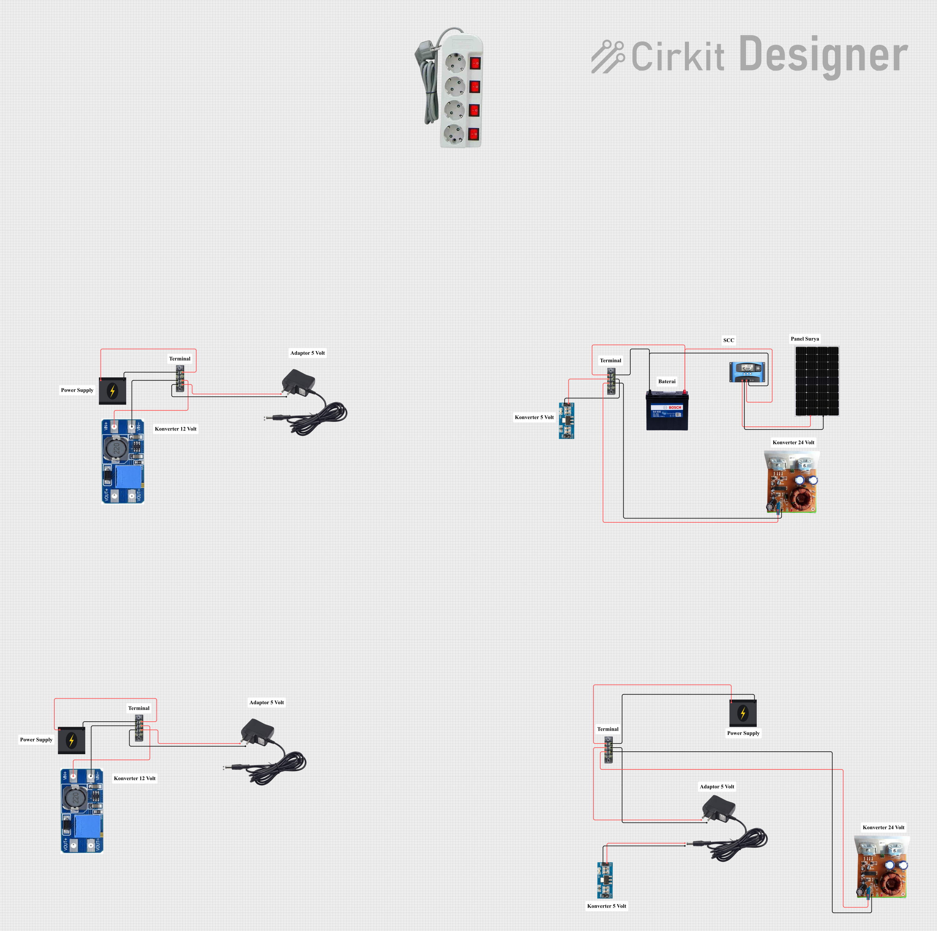
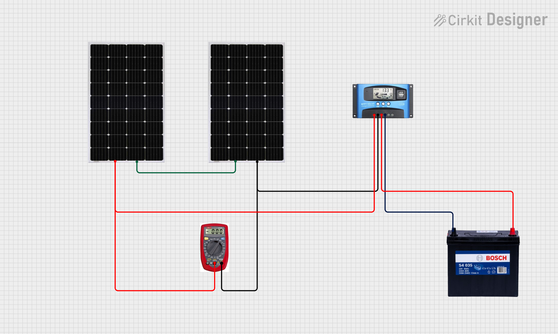
Explore Projects Built with Solar Panel Regulator 5A MPPT Controller Battery Charging 9V/12V/24V/Auto Switch
Common Applications and Use Cases
- Off-grid solar power systems for homes, RVs, and boats
- Solar-powered battery charging for 9V, 12V, and 24V systems
- Renewable energy projects requiring efficient power management
- Portable solar charging stations for outdoor activities
Technical Specifications
Key Technical Details
- Input Voltage Range: 9V to 50V DC
- Output Voltage Levels: 9V, 12V, 24V (auto-switching)
- Maximum Current: 5A
- Efficiency: Up to 98% (MPPT optimized)
- Battery Compatibility: Lead-acid, lithium-ion, and other rechargeable batteries
- Operating Temperature Range: -20°C to 60°C
- Protection Features: Overcharge, over-discharge, short-circuit, and reverse polarity protection
Pin Configuration and Descriptions
The Solar Panel Regulator has the following input/output terminals:
| Pin/Terminal | Label | Description |
|---|---|---|
| 1 | Solar Panel (+) | Positive input terminal for connecting the solar panel. |
| 2 | Solar Panel (-) | Negative input terminal for connecting the solar panel. |
| 3 | Battery (+) | Positive output terminal for connecting the battery. |
| 4 | Battery (-) | Negative output terminal for connecting the battery. |
| 5 | Load (+) | Positive terminal for connecting a DC load (optional). |
| 6 | Load (-) | Negative terminal for connecting a DC load (optional). |
Usage Instructions
How to Use the Component in a Circuit
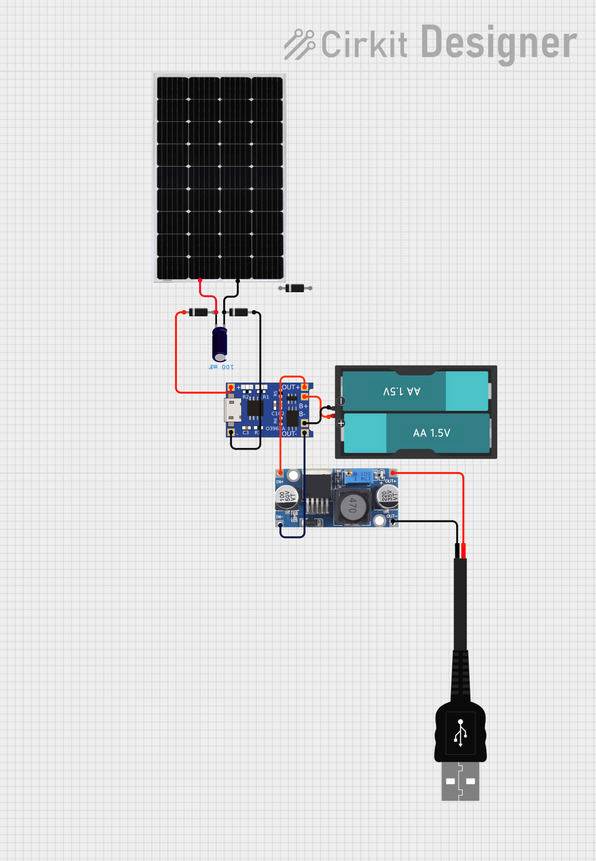
Connect the Solar Panel:
- Attach the positive and negative terminals of the solar panel to the
Solar Panel (+)andSolar Panel (-)inputs on the regulator. - Ensure the solar panel's voltage is within the input range (9V to 50V DC).
- Attach the positive and negative terminals of the solar panel to the
Connect the Battery:
- Connect the positive and negative terminals of the battery to the
Battery (+)andBattery (-)outputs on the regulator. - Verify that the battery type is compatible with the regulator (e.g., lead-acid or lithium-ion).
- Connect the positive and negative terminals of the battery to the
Optional Load Connection:
- If you wish to power a DC load directly, connect the load's positive and negative terminals to the
Load (+)andLoad (-)outputs.
- If you wish to power a DC load directly, connect the load's positive and negative terminals to the
Power On:
- Once all connections are secure, the regulator will automatically detect the battery voltage and switch to the appropriate charging mode (9V, 12V, or 24V).
Monitor Operation:
- Use the built-in LED indicators (if available) or an external monitoring system to check the charging status and ensure proper operation.
Important Considerations and Best Practices
- Ensure Proper Polarity: Always double-check the polarity of the connections to avoid damage to the regulator or connected devices.
- Use Appropriate Wire Gauges: Select wires that can handle the maximum current (5A) without overheating.
- Avoid Overloading: Do not exceed the regulator's maximum current rating of 5A.
- Place in a Ventilated Area: Install the regulator in a location with adequate airflow to prevent overheating.
- Regular Maintenance: Periodically inspect the connections and clean the terminals to ensure optimal performance.
Arduino UNO Integration Example
If you want to monitor the battery voltage using an Arduino UNO, you can connect the battery output to an analog input pin on the Arduino. Below is an example code snippet:
// Define the analog pin connected to the battery's positive terminal
const int batteryPin = A0;

void setup() {
  Serial.begin(9600); // Initialize serial communication at 9600 baud
}

void loop() {
  int sensorValue = analogRead(batteryPin); // Read the analog value
  float voltage = sensorValue * (5.0 / 1023.0) * 6;
  // Convert the analog value to voltage. Adjust the multiplier (6) based on
  // the voltage divider circuit used to step down the battery voltage.

  Serial.print("Battery Voltage: ");
  Serial.print(voltage);
  Serial.println(" V");

  delay(1000); // Wait for 1 second before the next reading
}
Note: Use a voltage divider circuit to step down the battery voltage to a safe level (0-5V) for the Arduino's analog input.
Troubleshooting and FAQs
Common Issues and Solutions
No Output Voltage:
- Cause: Incorrect wiring or loose connections.
- Solution: Double-check all connections and ensure proper polarity.
Overheating Regulator:
- Cause: Insufficient ventilation or excessive current draw.
- Solution: Place the regulator in a well-ventilated area and ensure the load does not exceed 5A.
Battery Not Charging:
- Cause: Incompatible battery type or damaged battery.
- Solution: Verify the battery type and replace it if necessary.
Fluctuating Output Voltage:
- Cause: Insufficient solar panel input or shading.
- Solution: Ensure the solar panel is receiving adequate sunlight and is not obstructed.
FAQs
Q: Can this regulator charge multiple batteries simultaneously?
A: No, the regulator is designed to charge a single battery at a time.Q: Does the regulator support lithium iron phosphate (LiFePO4) batteries?
A: Yes, as long as the battery voltage is within the supported range.Q: Can I use this regulator with a 48V solar panel?
A: No, the input voltage must not exceed 50V, and 48V panels may exceed this limit under certain conditions.Q: How do I know if the regulator is working properly?
A: Check the LED indicators (if available) or use a multimeter to measure the output voltage and current.
By following this documentation, you can effectively use the Solar Panel Regulator 5A MPPT Controller for efficient solar energy management and battery charging.