How to Use Ubiquiti UniFI USW Flex Mini 5-Port Ethernet Switch: Examples, Pinouts, and Specs
Introduction
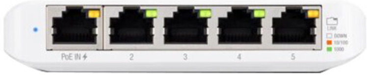
The Ubiquiti UniFi USW Flex Mini 5-Port Ethernet Switch is a compact, managed Ethernet switch designed for seamless integration into home and small office networks. It features five Gigabit Ethernet ports, including one port with Power over Ethernet (PoE) input support, allowing for flexible deployment without the need for a dedicated power adapter. This switch is part of the UniFi ecosystem, enabling centralized configuration and monitoring through the UniFi Network Controller.
Explore Projects Built with Ubiquiti UniFI USW Flex Mini 5-Port Ethernet Switch


Explore Projects Built with Ubiquiti UniFI USW Flex Mini 5-Port Ethernet Switch
Common Applications and Use Cases
- Expanding wired network connectivity in home or small office environments.
- Connecting multiple devices such as computers, printers, and IP cameras.
- Integrating with the UniFi ecosystem for centralized network management.
- Deploying in locations where PoE simplifies installation by eliminating the need for additional power outlets.
Technical Specifications
Below are the key technical details of the Ubiquiti UniFi USW Flex Mini 5-Port Ethernet Switch:
| Specification | Details |
|---|---|
| Manufacturer | Ubiquiti |
| Part ID | Ethernet Switch |
| Ports | 5 Gigabit Ethernet ports |
| PoE Input Support | 802.3af/at PoE input on Port 1 |
| Power Supply | USB-C power adapter (optional, included) |
| Switching Capacity | 10 Gbps |
| Forwarding Rate | 7.44 Mpps |
| VLAN Support | 802.1Q VLAN tagging |
| Management Interface | UniFi Network Controller (web or mobile app) |
| Operating Temperature | 0°C to 40°C (32°F to 104°F) |
| Dimensions | 107.16 x 70.15 x 21.17 mm (4.22 x 2.76 x 0.83 inches) |
| Weight | 150 g (5.29 oz) |
Port Configuration and Descriptions
The following table describes the functionality of each port:
| Port Number | Type | Description |
|---|---|---|
| Port 1 | Gigabit Ethernet (PoE) | Supports 802.3af/at PoE input for powering the switch. |
| Ports 2-5 | Gigabit Ethernet | Standard Gigabit Ethernet ports for connecting devices. |
| USB-C | Power Input | Optional USB-C power input for powering the switch when PoE is not available. |
Usage Instructions
How to Use the Component in a Network
Powering the Switch:
- Connect a PoE-enabled Ethernet cable to Port 1 to power the switch and provide network connectivity.
- Alternatively, use the included USB-C power adapter to power the switch if PoE is not available.
Connecting Devices:
- Use Ports 2-5 to connect devices such as computers, printers, or IP cameras.
- Ensure that Ethernet cables are securely plugged into the ports.
Configuring the Switch:
- Download and install the UniFi Network Controller software on your computer or mobile device.
- Connect the switch to the same network as the UniFi Controller.
- Launch the UniFi Controller and adopt the switch into your network for centralized management.
- Configure VLANs, port settings, and other features as needed.
Monitoring and Management:
- Use the UniFi Controller to monitor network traffic, view connected devices, and manage switch settings.
- Access the controller via a web browser or the UniFi mobile app.
Important Considerations and Best Practices
- Ensure that the PoE source provides sufficient power for the switch and any connected devices.
- Use high-quality Ethernet cables to ensure reliable connectivity and performance.
- Regularly update the UniFi Controller software and switch firmware to access the latest features and security updates.
- Avoid exposing the switch to extreme temperatures or moisture to maintain optimal performance.
Example: Connecting to an Arduino UNO
While the UniFi USW Flex Mini is not directly used with microcontrollers like the Arduino UNO, it can be part of a network that connects an Arduino to other devices. For example, you can use the switch to connect an Arduino with an Ethernet shield to a local network for IoT applications.
#include <SPI.h>
#include <Ethernet.h>

// MAC address and IP address for the Arduino Ethernet Shield
byte mac[] = { 0xDE, 0xAD, 0xBE, 0xEF, 0xFE, 0xED };
IPAddress ip(192, 168, 1, 177); // Replace with your network's IP range

// Initialize the Ethernet client
EthernetClient client;

void setup() {
  // Start the Ethernet connection
  if (Ethernet.begin(mac) == 0) {
    // If DHCP fails, use the static IP address
    Ethernet.begin(mac, ip);
  }
  Serial.begin(9600);
  while (!Serial) {
    ; // Wait for the serial port to connect
  }
  Serial.println("Ethernet connected!");
}

void loop() {
  // Example: Send data to a server
  if (client.connect("example.com", 80)) {
    client.println("GET / HTTP/1.1");
    client.println("Host: example.com");
    client.println("Connection: close");
    client.println();
  }
  delay(1000);
}
Troubleshooting and FAQs
Common Issues and Solutions
Switch Not Powering On:
- Ensure that the PoE source is active and compatible with 802.3af/at standards.
- If using the USB-C power adapter, verify that it is properly connected and functional.
Devices Not Connecting:
- Check that Ethernet cables are securely plugged into the ports.
- Verify that the connected devices are powered on and configured correctly.
Switch Not Detected in UniFi Controller:
- Ensure that the switch is connected to the same network as the UniFi Controller.
- Restart the switch and the UniFi Controller software.
- Check for firmware updates and apply them if necessary.
Slow Network Speeds:
- Verify that all connected devices support Gigabit Ethernet.
- Use high-quality Ethernet cables to avoid signal degradation.
FAQs
Q: Can the switch be powered by both PoE and USB-C simultaneously?
A: No, the switch will prioritize PoE input if both power sources are connected.
Q: Does the switch support unmanaged mode?
A: No, the switch is designed to be managed through the UniFi Network Controller.
Q: Can I use this switch with non-UniFi devices?
A: Yes, the switch is compatible with any Ethernet-enabled device, but advanced features require the UniFi Controller.
Q: Is the switch wall-mountable?
A: No, the switch is designed for desktop use and does not include wall-mounting hardware.