How to Use MCP48X2: Examples, Pinouts, and Specs

 Design with MCP48X2 in Cirkit Designer
Introduction
The MCP48X2 is a dual 12-bit digital-to-analog converter (DAC) manufactured by Microchip. It is designed to convert digital signals into precise analog voltages, making it ideal for applications requiring high-resolution analog output. The device features an I2C interface for easy communication with microcontrollers and other digital systems. Additionally, it includes an integrated voltage reference and operates with low power consumption, making it suitable for portable and battery-powered devices.
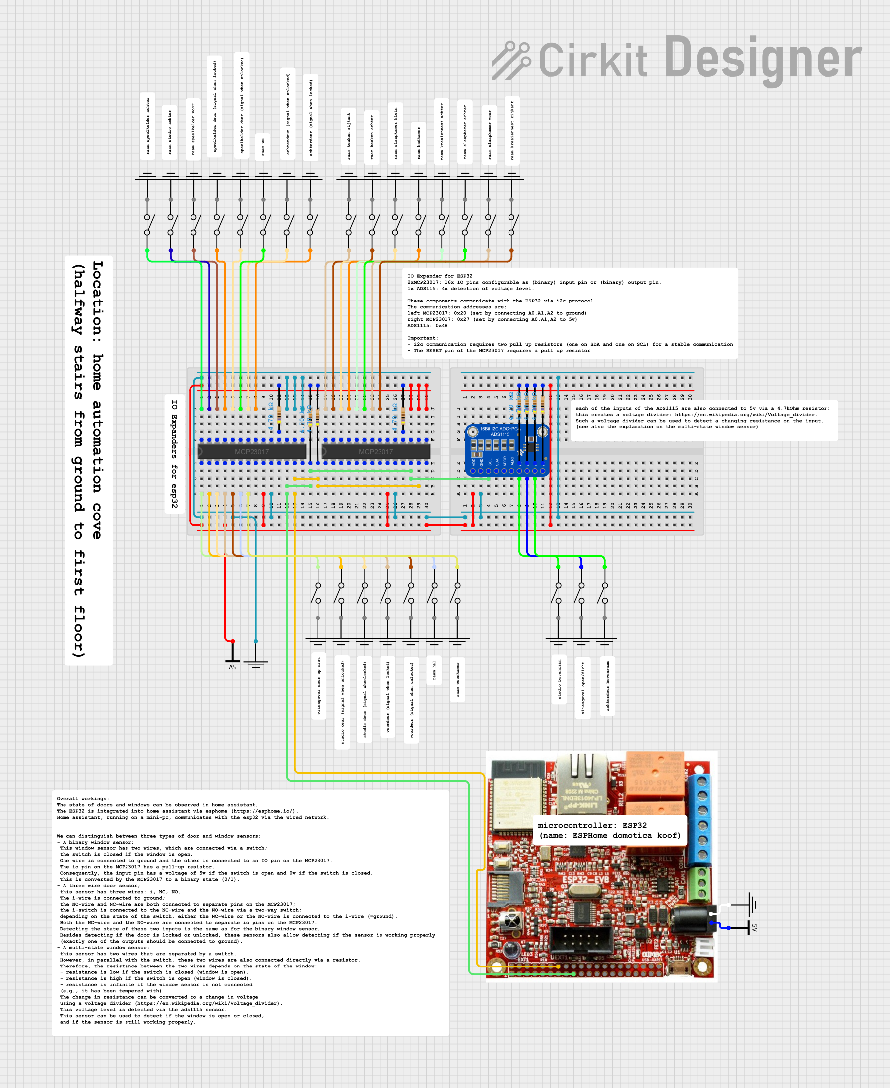
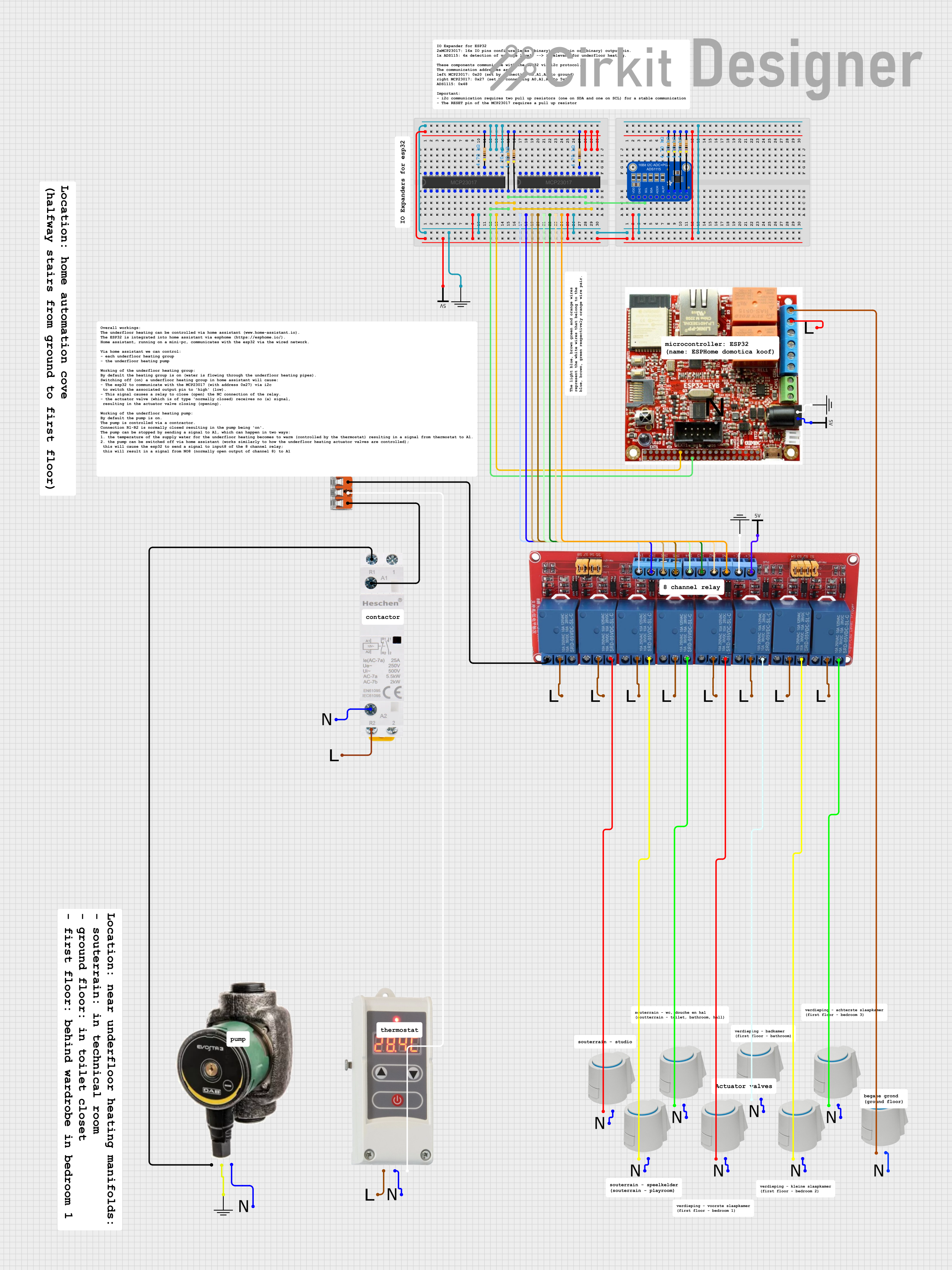
Explore Projects Built with MCP48X2

 Open Project in Cirkit Designer
 Open Project in Cirkit Designer
 Open Project in Cirkit Designer
 Open Project in Cirkit Designer
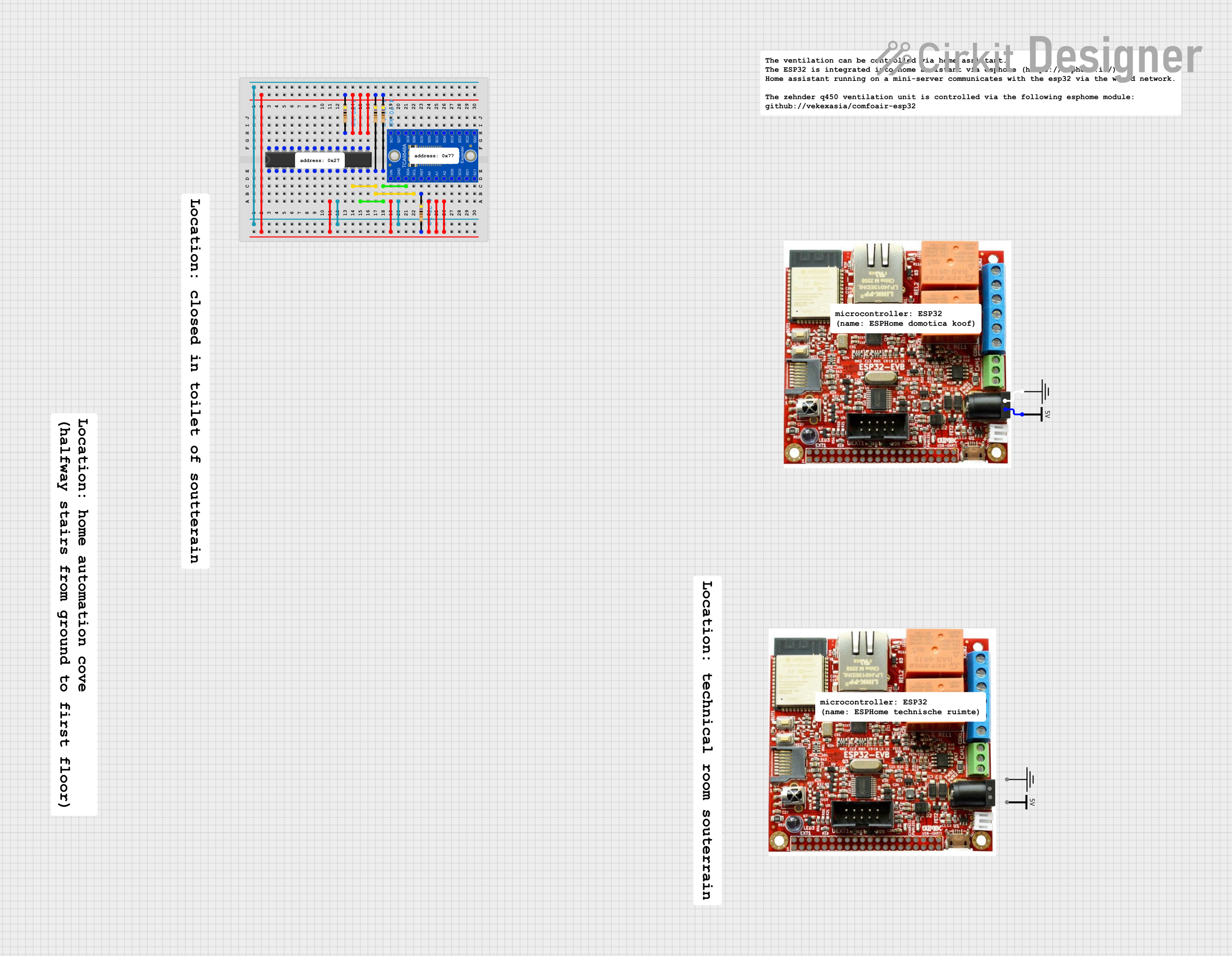
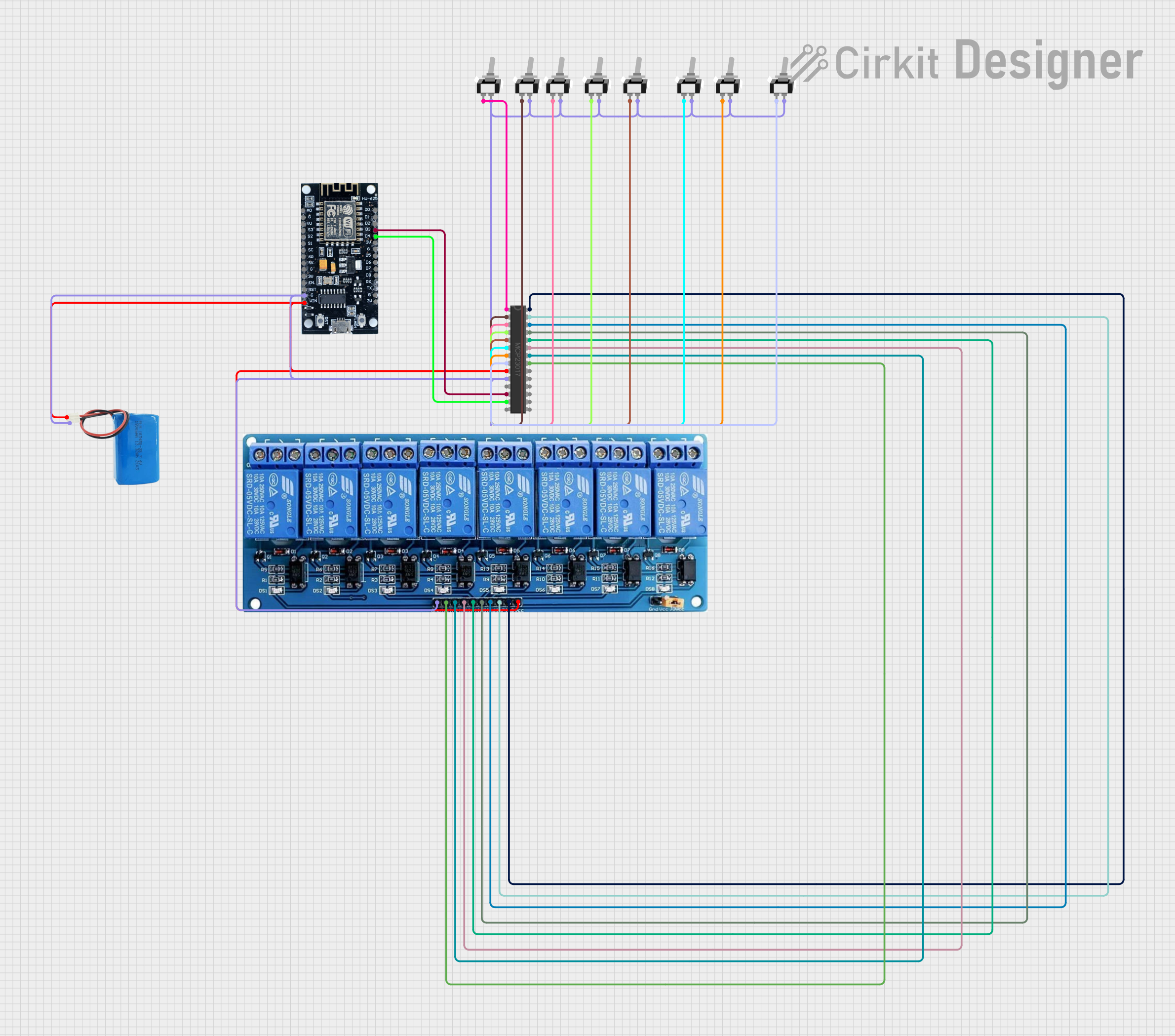
Explore Projects Built with MCP48X2

 Open Project in Cirkit Designer
 Open Project in Cirkit Designer
 Open Project in Cirkit Designer
 Open Project in Cirkit Designer
Common Applications and Use Cases
- Audio signal generation and processing
- Industrial process control
- Portable medical devices
- Data acquisition systems
- Precision instrumentation
- Signal reconstruction in communication systems
Technical Specifications
The MCP48X2 is available in multiple variants, such as MCP4822 (12-bit resolution), MCP4812 (10-bit resolution), and MCP4802 (8-bit resolution). Below are the key technical details for the MCP48X2 series:
Key Technical Details
- Resolution: 12-bit (MCP4822), 10-bit (MCP4812), or 8-bit (MCP4802)
- Interface: I2C (Inter-Integrated Circuit)
- Supply Voltage: 2.7V to 5.5V
- Output Voltage Range: 0V to VREF (internal or external reference)
- Integrated Voltage Reference: 2.048V (optional)
- Power Consumption: Low-power operation with shutdown mode
- Output Type: Buffered voltage output
- Temperature Range: -40°C to +125°C
- Package Options: 8-pin PDIP, SOIC, and MSOP
Pin Configuration and Descriptions
The MCP48X2 is typically available in an 8-pin package. Below is the pinout and description:
| Pin Number | Pin Name | Description |
|---|---|---|
| 1 | VDD | Positive power supply (2.7V to 5.5V) |
| 2 | CS | Chip Select (active low) |
| 3 | SCK | Serial Clock Input (used for SPI communication) |
| 4 | SDI | Serial Data Input (used to send data to the DAC) |
| 5 | LDAC | Load DAC (active low, updates the DAC output when toggled) |
| 6 | VOUTA | Analog output for channel A |
| 7 | VOUTB | Analog output for channel B |
| 8 | VSS | Ground (0V reference) |
Usage Instructions
How to Use the MCP48X2 in a Circuit
- Power Supply: Connect the VDD pin to a stable power source (2.7V to 5.5V) and the VSS pin to ground.
- SPI Communication: Use the CS, SCK, and SDI pins to interface with a microcontroller via the SPI protocol. Ensure the SPI clock frequency is within the device's specifications.
- Output Connections: Connect the VOUTA and VOUTB pins to the desired analog output circuits.
- Load DAC: Use the LDAC pin to update the DAC outputs. This pin can be tied low for automatic updates or controlled by the microcontroller for manual updates.
- Voltage Reference: Configure the device to use the internal 2.048V reference or an external reference voltage, depending on your application requirements.
Important Considerations and Best Practices
- Bypass Capacitor: Place a 0.1µF ceramic capacitor close to the VDD pin to filter noise and ensure stable operation.
- SPI Configuration: Set the SPI mode to Mode 0 (CPOL = 0, CPHA = 0) for proper communication with the MCP48X2.
- Output Loading: Avoid excessive loading on the VOUTA and VOUTB pins to maintain output accuracy.
- Thermal Management: Ensure adequate ventilation or heat dissipation if the device operates in high-temperature environments.
Example Code for Arduino UNO
Below is an example of how to interface the MCP48X2 with an Arduino UNO using SPI:
#include <SPI.h>

// Define MCP48X2 pins
const int CS_PIN = 10; // Chip Select pin connected to Arduino pin 10

void setup() {
  // Initialize SPI communication
  SPI.begin();
  SPI.setClockDivider(SPI_CLOCK_DIV16); // Set SPI clock speed
  SPI.setDataMode(SPI_MODE0);           // Set SPI mode to Mode 0
  pinMode(CS_PIN, OUTPUT);              // Set CS pin as output
  digitalWrite(CS_PIN, HIGH);           // Set CS pin high (inactive)
}

void loop() {
  // Example: Set DAC channel A to mid-scale (2048 for 12-bit resolution)
  uint16_t dacValue = 2048; // 12-bit value (0 to 4095)
  writeDAC(0, dacValue);    // Write to channel A
  delay(1000);              // Wait 1 second
}

// Function to write data to the MCP48X2
void writeDAC(uint8_t channel, uint16_t value) {
  // Prepare the 16-bit data packet
  uint16_t command = 0x3000; // Default command for MCP48X2
  command |= (channel << 15); // Set channel (0 for A, 1 for B)
  command |= (value & 0x0FFF); // Set the 12-bit DAC value

  // Send the data via SPI
  digitalWrite(CS_PIN, LOW); // Activate CS
  SPI.transfer16(command);   // Send 16-bit command
  digitalWrite(CS_PIN, HIGH); // Deactivate CS
}
Troubleshooting and FAQs
Common Issues and Solutions
No Output Voltage on VOUTA or VOUTB:
- Ensure the power supply (VDD) is within the specified range (2.7V to 5.5V).
- Verify that the SPI communication is correctly configured (Mode 0, proper clock speed).
- Check the LDAC pin configuration. If it is not tied low, ensure it is toggled to update the DAC output.
Incorrect Output Voltage:
- Confirm that the input digital value is within the valid range for the selected resolution (e.g., 0 to 4095 for 12-bit).
- Verify the reference voltage configuration (internal or external) and ensure it matches your design.
Device Not Responding to SPI Commands:
- Check the connections to the CS, SCK, and SDI pins.
- Ensure the CS pin is toggled correctly (active low) during SPI communication.
- Verify that the SPI clock frequency does not exceed the device's maximum limit.
FAQs
Q: Can I use the MCP48X2 with a 3.3V microcontroller?
A: Yes, the MCP48X2 operates with a supply voltage range of 2.7V to 5.5V, making it compatible with 3.3V systems.
Q: What is the difference between the MCP4822, MCP4812, and MCP4802?
A: The primary difference is the resolution: MCP4822 has 12-bit resolution, MCP4812 has 10-bit, and MCP4802 has 8-bit.
Q: How do I select between the internal and external voltage reference?
A: The voltage reference is configured via the control bits in the SPI command. Refer to the device datasheet for details on setting these bits.
Q: Can I leave the LDAC pin unconnected?
A: Yes, the LDAC pin can be tied low for automatic updates. If left unconnected, ensure it is pulled low internally or externally when needed.