How to Use Digital Flow Switch: Examples, Pinouts, and Specs
Introduction
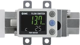
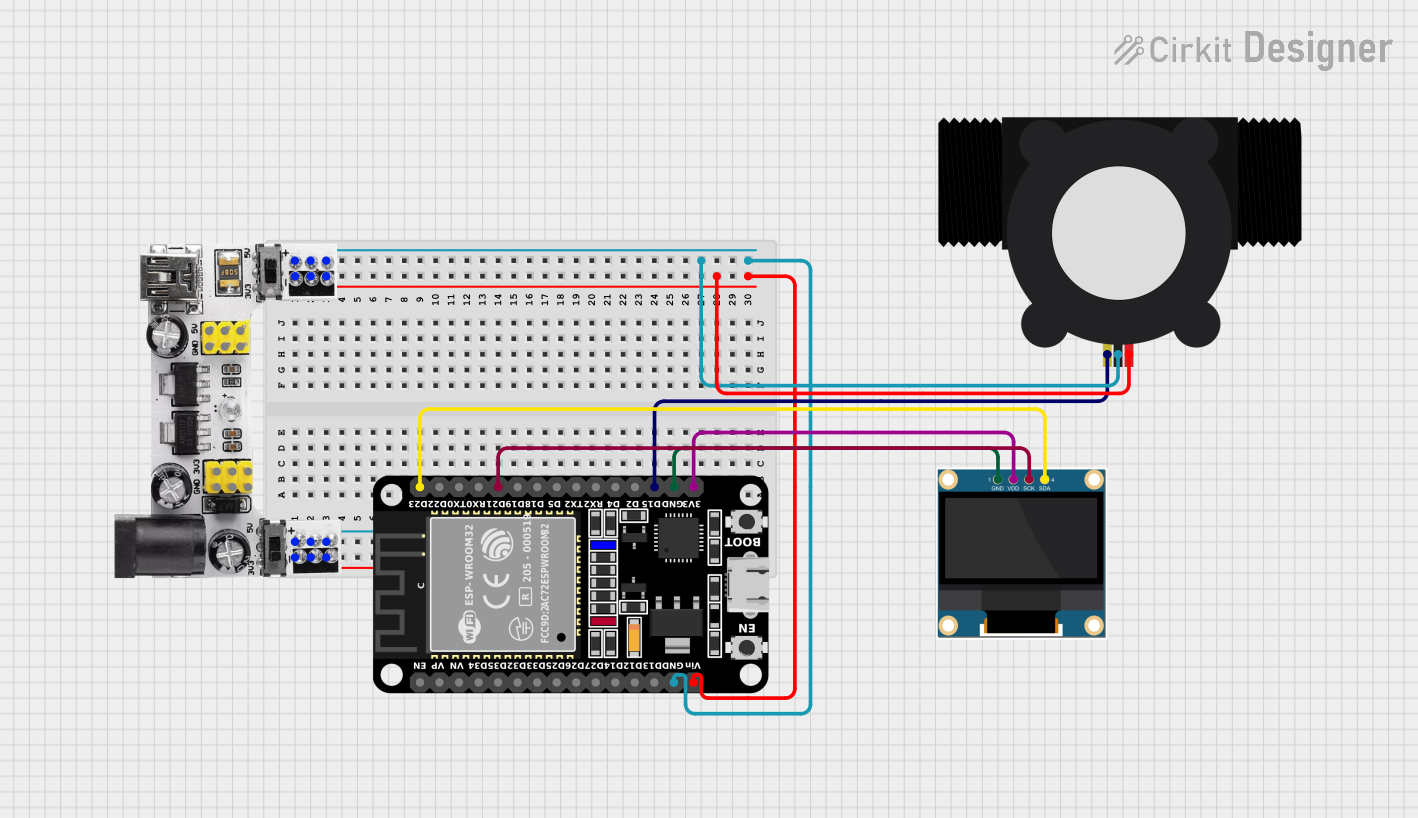
The PF3W720-04-C-M is a digital flow switch manufactured by SMC, designed to monitor and control the flow of fluids within a system. This component is commonly used in industrial applications, such as automation, water treatment, and chemical processing, where precise flow management is critical. It provides real-time monitoring and can be integrated into control systems to ensure optimal performance and safety.
Explore Projects Built with Digital Flow Switch
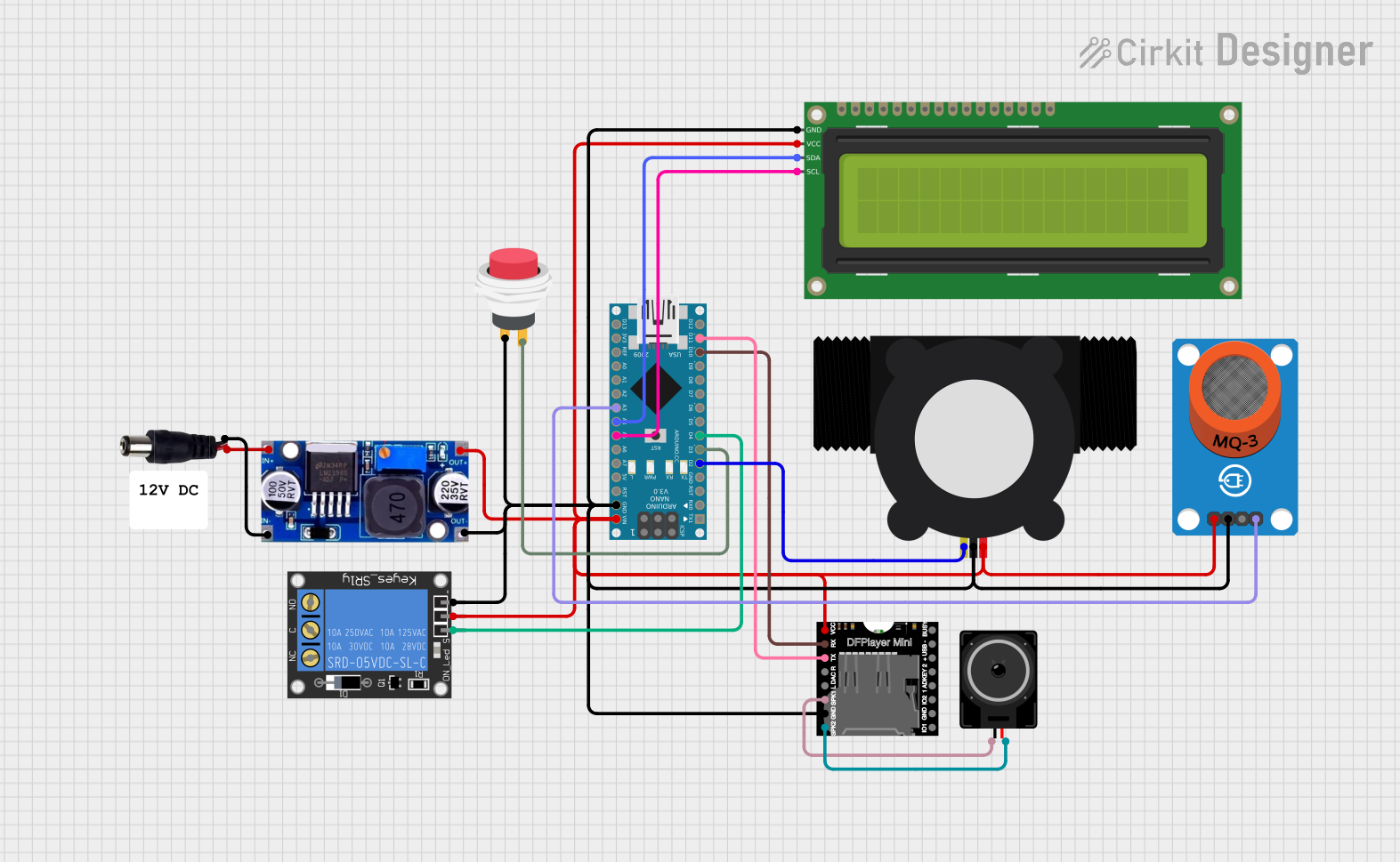
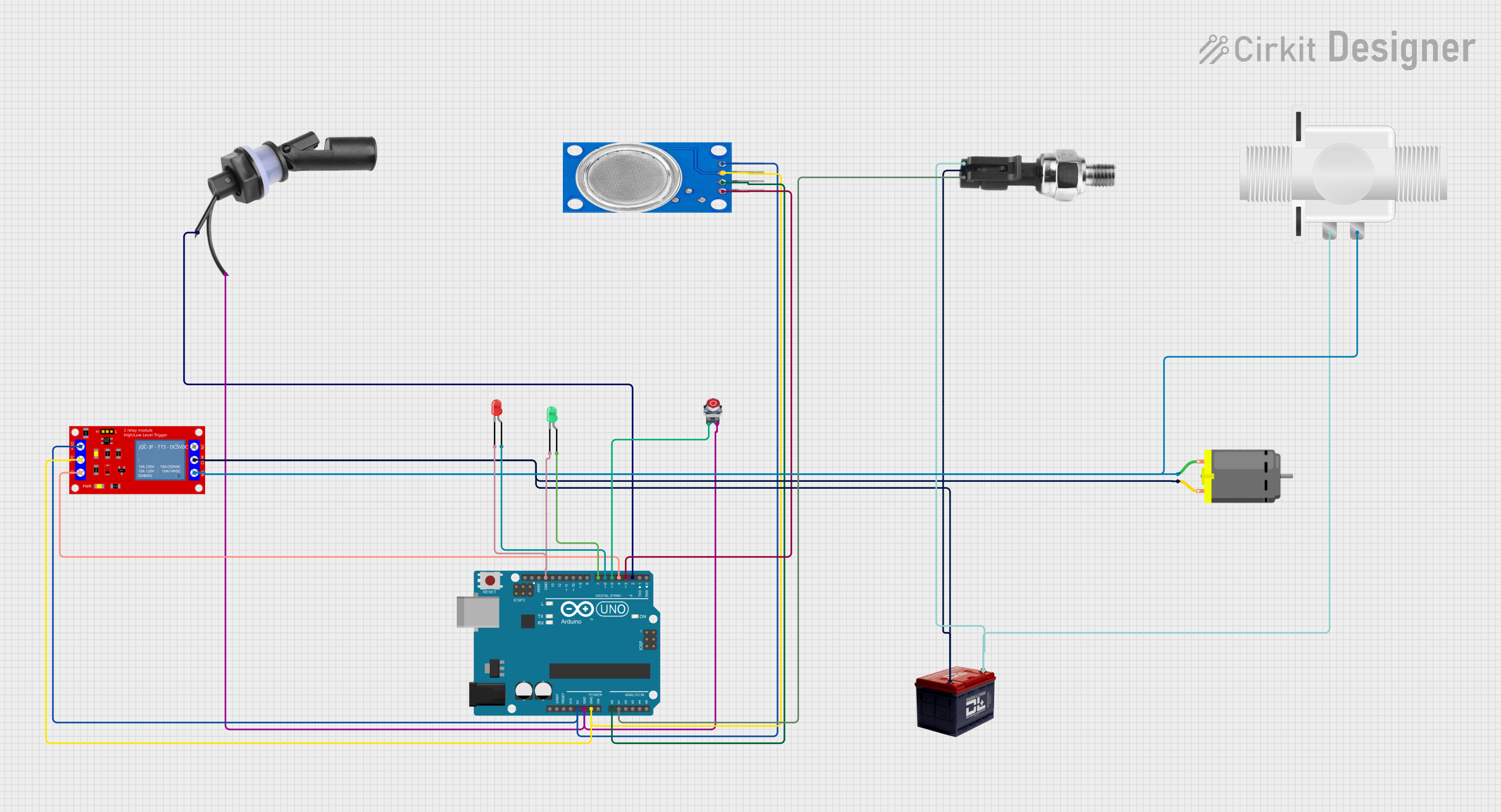
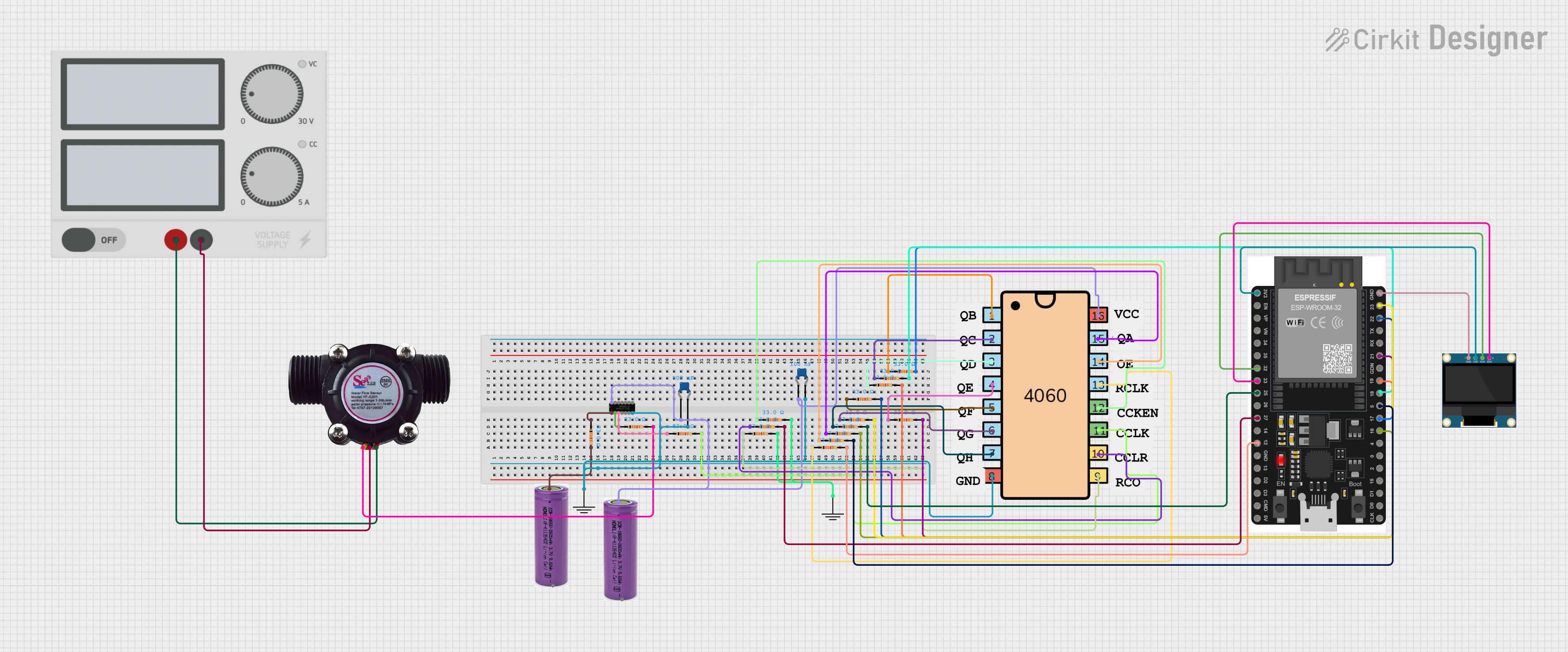
Explore Projects Built with Digital Flow Switch
Technical Specifications
General Specifications
- Manufacturer: SMC Corporation
- Part ID: PF3W720-04-C-M
- Type: Digital Flow Switch
- Flow Medium: Water
- Applicable Fluid Temperature: 0 to 85°C
- Flow Rate Range: 0.1 to 100 L/min
- Output: NPN or PNP (Selectable)
- Supply Voltage: 12 to 24 VDC ±10%
- Maximum Power Consumption: 40 mA or less
- Display: 3-digit, 7-segment LED
Pin Configuration and Descriptions
| Pin Number | Description | Notes |
|---|---|---|
| 1 | Power Supply (+V) | 12 to 24 VDC |
| 2 | Output 1 (Flow Rate Output) | NPN/PNP open collector output |
| 3 | Output 2 (Alarm Output) | NPN/PNP open collector output |
| 4 | Input (External Input) | For zero-cut, response time etc. |
| 5 | Ground (-V) |
Usage Instructions
Integration into a Circuit
- Power Supply: Connect the power supply to pins 1 (+V) and 5 (-V), ensuring that the voltage is within the specified range (12 to 24 VDC).
- Output Connections: Connect Output 1 and Output 2 to your control system or monitoring device. Choose between NPN or PNP output based on your system requirements.
- Input Signal: Use the Input pin to set up external control features such as zero-cut or to adjust the response time.
Best Practices
- Ensure that the fluid temperature and flow rate are within the specified limits to prevent damage to the switch.
- Use shielded cables for power and output connections to minimize electrical noise.
- Regularly calibrate the switch to maintain accuracy.
- Avoid exposing the switch to corrosive or overly viscous fluids that are not compatible with its construction.
Troubleshooting and FAQs
Common Issues
- No Output Signal: Check the power supply and wiring connections. Ensure the flow rate is within the detectable range.
- Inaccurate Readings: Verify that the switch is properly calibrated. Check for any air bubbles or debris in the fluid that may affect the sensor's accuracy.
FAQs
Q: Can the PF3W720-04-C-M be used with fluids other than water? A: This flow switch is calibrated for water. Using it with other fluids may require recalibration and could affect accuracy.
Q: What is the maximum pressure the flow switch can handle? A: Please refer to the manufacturer's datasheet for specific pressure ratings as they can vary based on the model and configuration.
Q: How do I switch between NPN and PNP output modes? A: The output mode can be selected using the settings on the device. Refer to the manufacturer's manual for detailed instructions.
Example Arduino UNO Connection
// Define the digital pins connected to the flow switch outputs
const int flowRateOutputPin = 2; // Output 1 from the flow switch
const int alarmOutputPin = 3;    // Output 2 from the flow switch

void setup() {
  pinMode(flowRateOutputPin, INPUT);
  pinMode(alarmOutputPin, INPUT);
  Serial.begin(9600);
}

void loop() {
  // Read the flow rate and alarm outputs
  int flowRateSignal = digitalRead(flowRateOutputPin);
  int alarmSignal = digitalRead(alarmOutputPin);

  // Output the status to the Serial Monitor
  Serial.print("Flow Rate Signal: ");
  Serial.println(flowRateSignal);
  Serial.print("Alarm Signal: ");
  Serial.println(alarmSignal);

  // Add a delay for readability
  delay(1000);
}
Note: This example assumes that the digital flow switch outputs are compatible with the input voltage levels of the Arduino UNO. Always consult the component datasheet and the Arduino specifications to ensure proper voltage levels and compatibility.