
How to Use ATS: Examples, Pinouts, and Specs
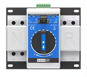
 Design with ATS in Cirkit Designer
Introduction
An Automatic Transfer Switch (ATS) is a critical device used in power management systems. It automatically transfers a power load between two power sources, typically switching between utility power and a backup generator. This ensures an uninterrupted power supply during outages or power failures. ATS devices are widely used in residential, commercial, and industrial applications where continuous power is essential.
Explore Projects Built with ATS
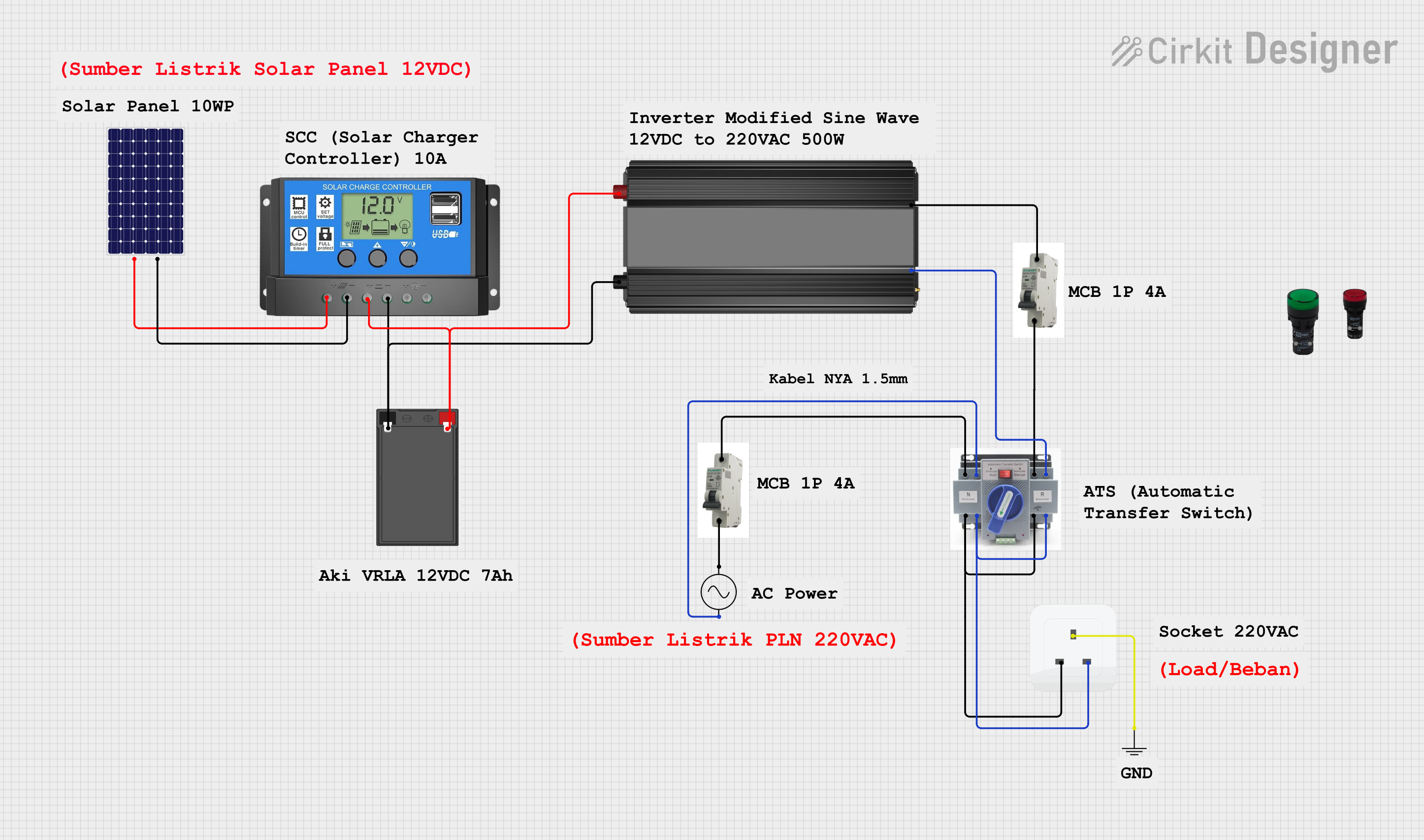 Open Project in Cirkit Designer
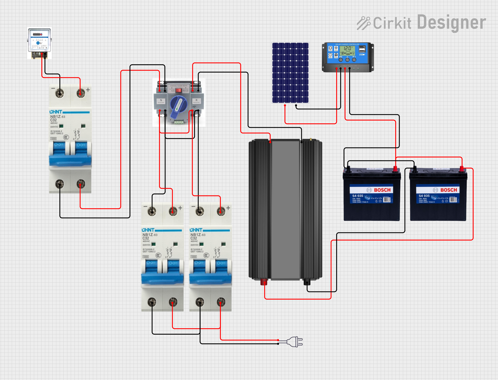 Open Project in Cirkit Designer
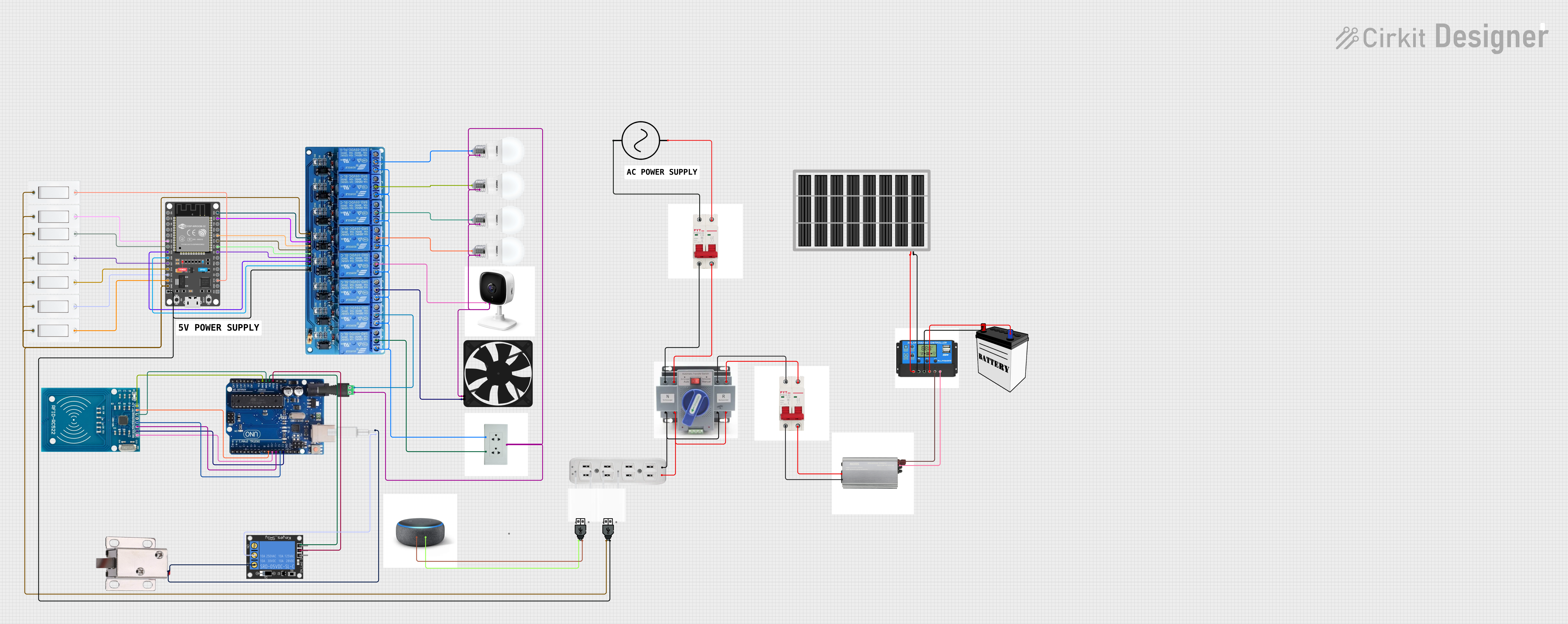 Open Project in Cirkit Designer
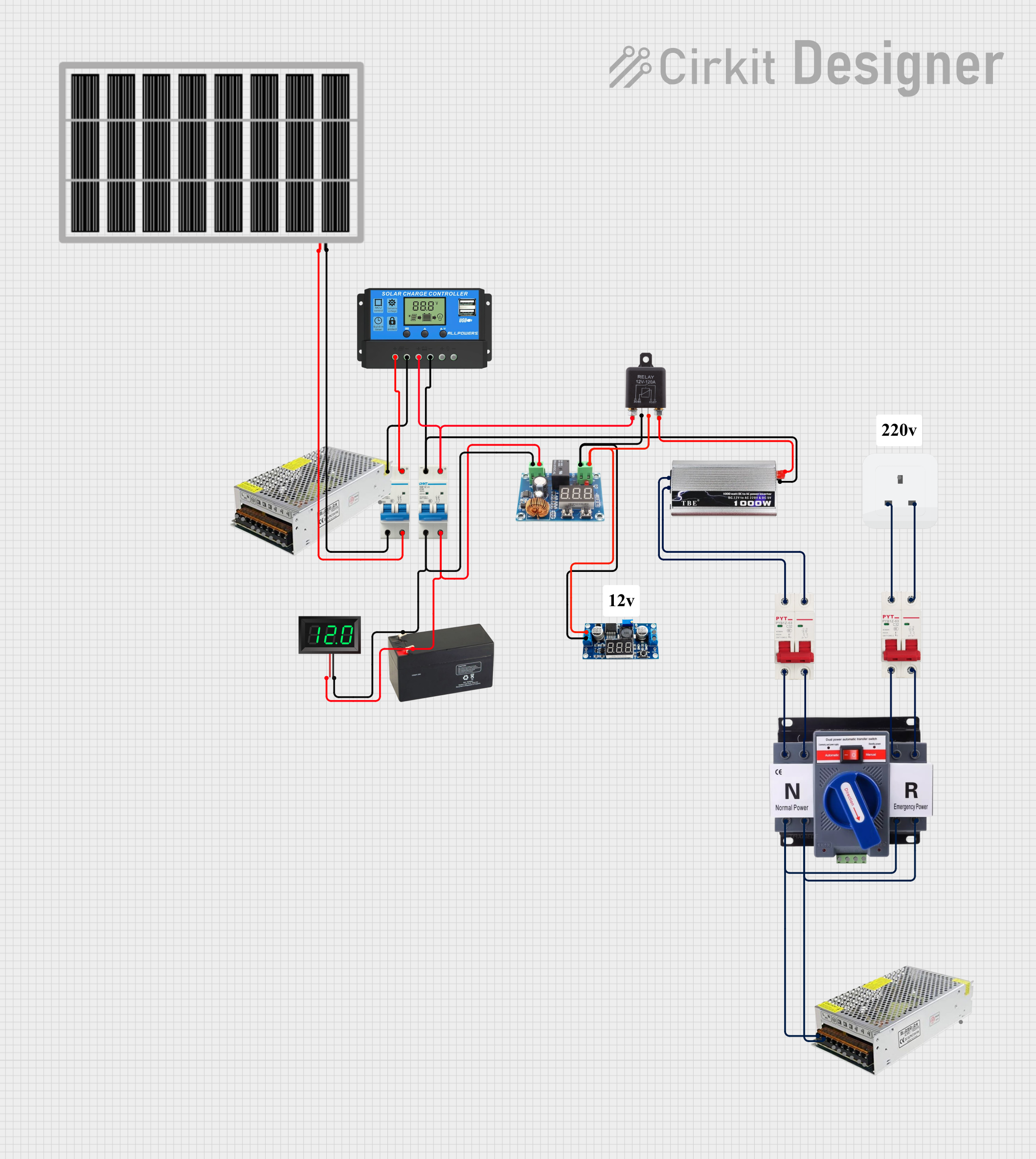 Open Project in Cirkit Designer
Explore Projects Built with ATS
Open Project in Cirkit DesignerOpen Project in Cirkit DesignerOpen Project in Cirkit DesignerOpen Project in Cirkit DesignerCommon Applications and Use Cases
- Backup power systems for homes, hospitals, and data centers
- Industrial facilities requiring uninterrupted power for machinery
- Telecommunications and IT infrastructure
- Emergency lighting systems
- Renewable energy systems with hybrid power sources
Technical Specifications
Below are the key technical details for a typical ATS. Note that specific models may vary slightly in their specifications.
General Specifications
| Parameter | Value |
|---|---|
| Rated Voltage | 120V, 240V, or 480V AC |
| Rated Current | 16A, 32A, 63A, or higher |
| Frequency | 50Hz / 60Hz |
| Switching Time | 1-10 seconds (typical) |
| Operating Temperature | -20°C to 60°C |
| Control Voltage | 12V DC, 24V DC, or 230V AC |
| Enclosure Rating | IP20, IP54, or IP65 |
Pin Configuration and Descriptions
The ATS typically has terminals for connecting the power sources, load, and control signals. Below is a general pin configuration:
| Pin/Terminal Label | Description |
|---|---|
| L1 (Utility Line) | Connects to the live wire of the utility power |
| N1 (Utility Neutral) | Connects to the neutral wire of the utility power |
| L2 (Generator Line) | Connects to the live wire of the generator |
| N2 (Generator Neutral) | Connects to the neutral wire of the generator |
| LOAD L | Live wire connection to the load |
| LOAD N | Neutral wire connection to the load |
| GND | Ground connection for safety |
| Control Input | Signal input for manual or automatic control |
Usage Instructions
How to Use the ATS in a Circuit
Power Source Connections:
- Connect the utility power lines (L1 and N1) to the corresponding terminals on the ATS.
- Connect the generator power lines (L2 and N2) to the ATS.
- Ensure proper grounding by connecting the GND terminal to the earth ground.
Load Connection:
- Connect the load's live and neutral wires to the LOAD L and LOAD N terminals.
Control Signal:
- If the ATS supports manual control, connect the control input to a switch or control panel.
- For automatic operation, ensure the ATS is configured to detect power loss from the utility source and automatically switch to the generator.
Testing:
- Test the ATS by simulating a power outage. Disconnect the utility power and verify that the ATS switches to the generator.
- Restore utility power and confirm that the ATS switches back to the utility source.
Important Considerations and Best Practices
- Safety First: Always disconnect power before wiring or servicing the ATS.
- Load Capacity: Ensure the ATS is rated for the total load current and voltage.
- Generator Compatibility: Verify that the generator's output matches the ATS's input specifications.
- Regular Maintenance: Periodically inspect the ATS for wear, loose connections, or damage.
- Compliance: Follow local electrical codes and standards when installing the ATS.
Example: Connecting an ATS to an Arduino UNO
An ATS can be monitored or controlled using an Arduino UNO. Below is an example code snippet to monitor the ATS status using digital inputs.
// Arduino code to monitor ATS status
const int utilityPin = 2;  // Pin connected to utility power status signal
const int generatorPin = 3; // Pin connected to generator power status signal

void setup() {
  pinMode(utilityPin, INPUT);  // Set utility pin as input
  pinMode(generatorPin, INPUT); // Set generator pin as input
  Serial.begin(9600);  // Initialize serial communication
}

void loop() {
  int utilityStatus = digitalRead(utilityPin);  // Read utility power status
  int generatorStatus = digitalRead(generatorPin); // Read generator power status

  if (utilityStatus == HIGH) {
    Serial.println("Utility power is active.");  // Print utility power status
  } else if (generatorStatus == HIGH) {
    Serial.println("Generator power is active.");  // Print generator power status
  } else {
    Serial.println("No power source is active.");  // Print no power status
  }

  delay(1000);  // Wait for 1 second before next reading
}
Troubleshooting and FAQs
Common Issues and Solutions
ATS Fails to Switch Power Sources:
- Cause: Incorrect wiring or insufficient control voltage.
- Solution: Verify all connections and ensure the control voltage matches the ATS specifications.
Frequent Switching Between Sources:
- Cause: Unstable utility power or generator output.
- Solution: Check the stability of the power sources and adjust the ATS sensitivity settings if possible.
Load Does Not Receive Power:
- Cause: Loose connections or faulty ATS.
- Solution: Inspect all connections and test the ATS with a multimeter.
ATS Overheats:
- Cause: Overloading or poor ventilation.
- Solution: Ensure the load does not exceed the ATS's rated capacity and provide adequate ventilation.
FAQs
Q1: Can the ATS be used with renewable energy sources like solar power?
A1: Yes, many ATS models support renewable energy sources. Ensure the ATS is compatible with the voltage and current output of the solar inverter.
Q2: How long does the ATS take to switch between sources?
A2: The switching time typically ranges from 1 to 10 seconds, depending on the model and configuration.
Q3: Is it possible to manually override the ATS?
A3: Yes, most ATS devices have a manual override option for maintenance or emergencies.
Q4: Can the ATS be installed outdoors?
A4: Only ATS models with a suitable enclosure rating (e.g., IP54 or IP65) should be installed outdoors. Ensure proper weatherproofing.
By following this documentation, users can effectively install, operate, and troubleshoot an Automatic Transfer Switch (ATS) for reliable power management.