How to Use 1-Channel Relay (5V 10A): Examples, Pinouts, and Specs
Introduction
The 1-Channel Relay (5V 10A) is an electronic switching device that allows you to control a high current circuit with a low voltage signal. This relay module is particularly useful in home automation, robotics, and industrial control systems where interfacing between low-level logic from microcontrollers and high-power loads is required.
Explore Projects Built with 1-Channel Relay (5V 10A)

Explore Projects Built with 1-Channel Relay (5V 10A)
Common Applications and Use Cases
- Home automation systems (e.g., turning lights or appliances on/off)
- Robotics (e.g., controlling motors or actuators)
- Industrial controls (e.g., starting/stopping heavy machinery)
- Automotive electronics (e.g., controlling car accessories)
Technical Specifications
Key Technical Details
- Control Voltage (Vcc): 5V DC
- Relay Operating Voltage: 250V AC or 30V DC
- Maximum Load: 10A @ 250V AC or 10A @ 30V DC
- Switching Type: SPDT (Single Pole Double Throw)
- Trigger Current: 15-20mA
- Isolation: Opto-isolated input
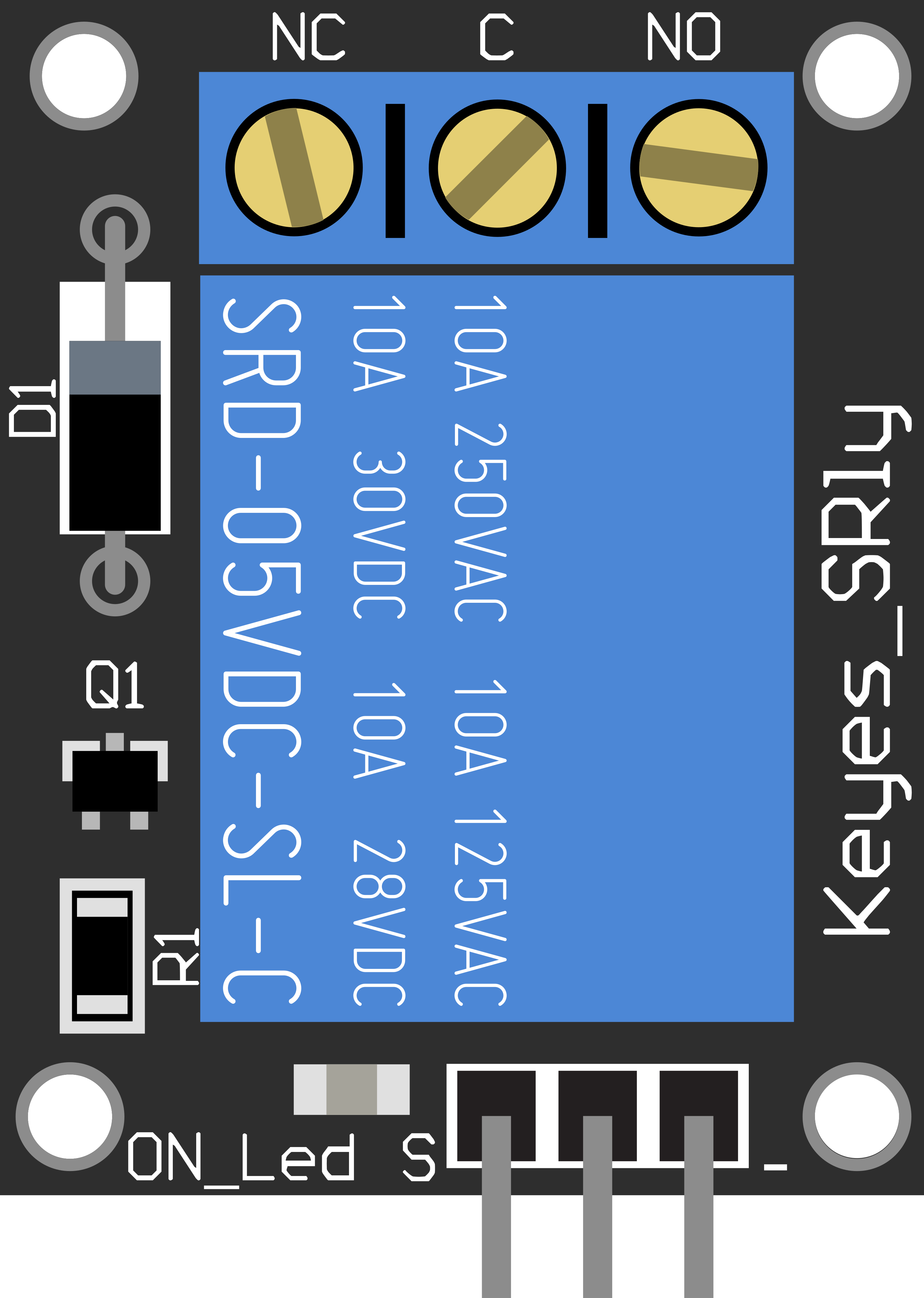
Pin Configuration and Descriptions
| Pin Number | Pin Name | Description |
|---|---|---|
| 1 | VCC | Connect to 5V power supply |
| 2 | GND | Connect to ground |
| 3 | IN | Control signal input (active LOW) |
| 4 | NO | Normally open contact to load |
| 5 | COM | Common contact to load |
| 6 | NC | Normally closed contact to load |
Usage Instructions
How to Use the Component in a Circuit
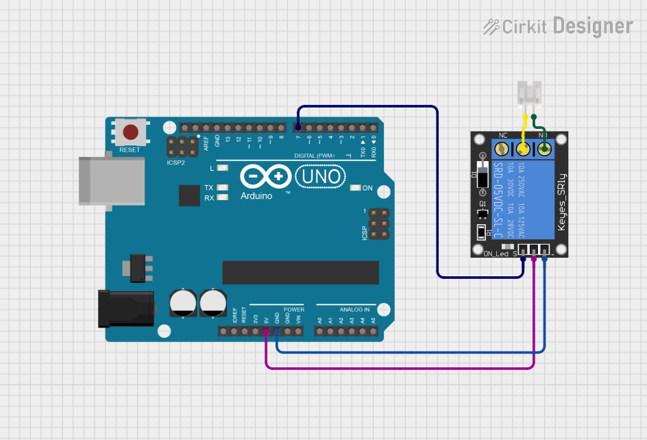
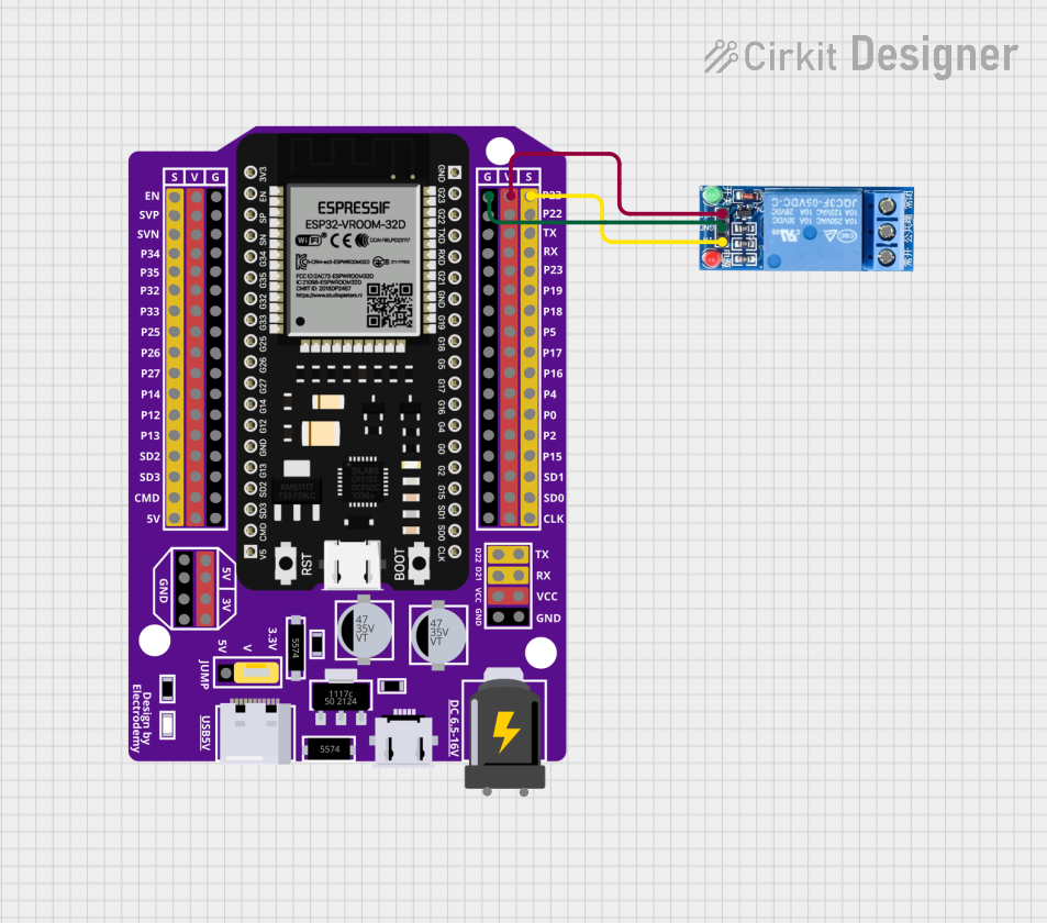
Power Connections:
- Connect the VCC pin to a 5V power supply.
- Connect the GND pin to the ground of the power supply.
Control Signal:
- Connect the IN pin to a digital output pin of a microcontroller, such as an Arduino.
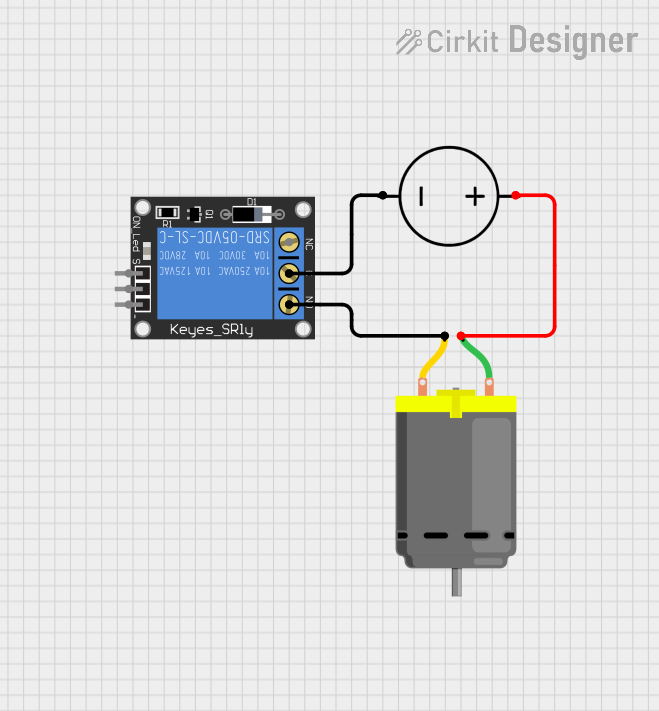
Load Connections:
- Connect the COM pin to one side of the load you wish to control.
- Connect either the NO or NC pin to the other side of the load, depending on whether you want the load to be powered when the relay is activated (NO) or deactivated (NC).
Important Considerations and Best Practices
- Ensure that the control signal voltage matches the relay's operating voltage (5V).
- Do not exceed the maximum load ratings to prevent damage to the relay and connected devices.
- Use appropriate wire sizes for high current loads to avoid overheating and potential fire hazards.
- Consider using a flyback diode when controlling inductive loads to prevent voltage spikes.
- Always ensure power is disconnected before making any changes to the wiring.
Example Code for Arduino UNO
// Define the relay control pin
const int relayPin = 2;

void setup() {
  // Set the relay pin as an output
  pinMode(relayPin, OUTPUT);
  // Start with the relay deactivated (Normally Open)
  digitalWrite(relayPin, HIGH);
}

void loop() {
  // Activate the relay
  digitalWrite(relayPin, LOW);
  delay(5000); // Keep the relay activated for 5 seconds
  // Deactivate the relay
  digitalWrite(relayPin, HIGH);
  delay(5000); // Keep the relay deactivated for 5 seconds
}
Troubleshooting and FAQs
Common Issues
- Relay does not switch: Check the control signal and power connections. Ensure the IN pin receives a LOW signal to activate.
- Load does not power on: Verify the load is properly connected to the NO or NC and COM pins. Also, check if the load exceeds the relay's maximum ratings.
- Intermittent operation: Inspect for loose connections or insufficient power supply to the relay module.
Solutions and Tips for Troubleshooting
- Use a multimeter to check for continuity across the relay contacts when activated.
- Ensure the power supply can deliver sufficient current for both the relay and the control circuit.
- If controlling multiple relays, consider using a separate power supply to prevent voltage drops.
FAQs
Q: Can I control this relay with a 3.3V signal? A: The relay is designed for a 5V control signal. A 3.3V signal may not reliably activate the relay.
Q: Is it safe to control AC mains with this relay? A: Yes, but ensure you have a solid understanding of working with high voltage and take all necessary safety precautions.
Q: Can I use PWM to control the relay? A: No, the relay requires a steady LOW signal to activate. PWM may cause erratic behavior.
Remember to always follow safety guidelines when working with electronics, especially when controlling high-power loads.