Cirkit Designer Logo
Cirkit Designer
Your all-in-one circuit design IDE
Home / 
Component Documentation

How to Use AVR32DA48: Examples, Pinouts, and Specs

Image of AVR32DA48
Cirkit Designer LogoDesign with AVR32DA48 in Cirkit Designer

Introduction

The AVR32DA48 is a 32-bit microcontroller developed by Microchip Technology. It is designed for low-power applications and offers a rich set of peripherals, including Analog-to-Digital Converters (ADCs), timers, and communication interfaces such as UART, SPI, and I2C. This microcontroller is part of the AVR DA family, which is known for its high performance, flexibility, and ease of use in embedded systems.

Explore Projects Built with AVR32DA48

Use Cirkit Designer to design, explore, and prototype these projects online. Some projects support real-time simulation. Click "Open Project" to start designing instantly!
Arduino Mega 2560-Controlled Stepper Motors with RFID Access and Traffic Light Indication
Image of Copy of test: A project utilizing AVR32DA48 in a practical application
This circuit controls two 28BYJ-48 stepper motors using A4988 stepper motor driver carriers, interfaced with an Arduino Mega 2560 microcontroller. It features an RFID-RC522 module for RFID reading, a 16x4 LCD display with I2C interface for user interaction, and a piezo speaker for audio feedback. Additionally, there is a traffic light module controlled by the Arduino, and a 48V to 5V converter to step down voltage for the logic levels. The power supply provides 12V to the motor drivers and is connected to a standard power outlet.
Cirkit Designer LogoOpen Project in Cirkit Designer
ATMEGA328 Battery-Powered LED Blinker with FTDI Programming
Image of Homemade Arduino using ATmega328: A project utilizing AVR32DA48 in a practical application
This circuit is a basic microcontroller setup using an ATMEGA328, powered by a 5V battery, and includes an FTDI programmer for serial communication. It features a pushbutton for reset functionality and two LEDs controlled by the microcontroller, with one LED blinking at a 1-second interval as programmed.
Cirkit Designer LogoOpen Project in Cirkit Designer
RFID-Activated Traffic Light Controller with Auditory Feedback Using Arduino Mega
Image of test: A project utilizing AVR32DA48 in a practical application
This circuit is designed to control two 28BYJ-48 stepper motors using A4988 stepper motor driver carriers, with an Arduino Mega 2560 as the central microcontroller. It includes an RFID-RC522 module for RFID reading, an LCD display for user interface, and a traffic light and piezo speaker for visual and audio signaling. The circuit is powered by a 12V 5A power supply, which is stepped down to 5V for logic level components, and it interfaces with a power outlet for AC to DC conversion.
Cirkit Designer LogoOpen Project in Cirkit Designer
ESP32-C3 Mini and MCP4725 DAC Controlled Analog Output Circuit
Image of pp: A project utilizing AVR32DA48 in a practical application
This circuit features an ESP32-C3 Mini microcontroller that interfaces with an Adafruit MCP4725 DAC via I2C for analog output, which is then fed into an OPA2333 operational amplifier. Power management is handled by a 5V step-down voltage regulator that receives power from a 2000mAh battery and supplies the ESP32-C3 and a 3.3V AMS1117 voltage regulator. Additionally, the circuit includes user input through buttons and electro pads, with debouncing provided by resistors.
Cirkit Designer LogoOpen Project in Cirkit Designer

Explore Projects Built with AVR32DA48

Use Cirkit Designer to design, explore, and prototype these projects online. Some projects support real-time simulation. Click "Open Project" to start designing instantly!
Image of Copy of test: A project utilizing AVR32DA48 in a practical application
Arduino Mega 2560-Controlled Stepper Motors with RFID Access and Traffic Light Indication
This circuit controls two 28BYJ-48 stepper motors using A4988 stepper motor driver carriers, interfaced with an Arduino Mega 2560 microcontroller. It features an RFID-RC522 module for RFID reading, a 16x4 LCD display with I2C interface for user interaction, and a piezo speaker for audio feedback. Additionally, there is a traffic light module controlled by the Arduino, and a 48V to 5V converter to step down voltage for the logic levels. The power supply provides 12V to the motor drivers and is connected to a standard power outlet.
Cirkit Designer LogoOpen Project in Cirkit Designer
Image of Homemade Arduino using ATmega328: A project utilizing AVR32DA48 in a practical application
ATMEGA328 Battery-Powered LED Blinker with FTDI Programming
This circuit is a basic microcontroller setup using an ATMEGA328, powered by a 5V battery, and includes an FTDI programmer for serial communication. It features a pushbutton for reset functionality and two LEDs controlled by the microcontroller, with one LED blinking at a 1-second interval as programmed.
Cirkit Designer LogoOpen Project in Cirkit Designer
Image of test: A project utilizing AVR32DA48 in a practical application
RFID-Activated Traffic Light Controller with Auditory Feedback Using Arduino Mega
This circuit is designed to control two 28BYJ-48 stepper motors using A4988 stepper motor driver carriers, with an Arduino Mega 2560 as the central microcontroller. It includes an RFID-RC522 module for RFID reading, an LCD display for user interface, and a traffic light and piezo speaker for visual and audio signaling. The circuit is powered by a 12V 5A power supply, which is stepped down to 5V for logic level components, and it interfaces with a power outlet for AC to DC conversion.
Cirkit Designer LogoOpen Project in Cirkit Designer
Image of pp: A project utilizing AVR32DA48 in a practical application
ESP32-C3 Mini and MCP4725 DAC Controlled Analog Output Circuit
This circuit features an ESP32-C3 Mini microcontroller that interfaces with an Adafruit MCP4725 DAC via I2C for analog output, which is then fed into an OPA2333 operational amplifier. Power management is handled by a 5V step-down voltage regulator that receives power from a 2000mAh battery and supplies the ESP32-C3 and a 3.3V AMS1117 voltage regulator. Additionally, the circuit includes user input through buttons and electro pads, with debouncing provided by resistors.
Cirkit Designer LogoOpen Project in Cirkit Designer

Common Applications and Use Cases

  • Home automation systems
  • Industrial control and monitoring
  • IoT (Internet of Things) devices
  • Consumer electronics
  • Motor control applications
  • Data acquisition systems

Technical Specifications

Key Technical Details

Parameter Value
Architecture 32-bit AVR
Operating Voltage 1.8V to 5.5V
Maximum Clock Speed 24 MHz
Flash Memory Up to 128 KB
SRAM Up to 16 KB
EEPROM 512 bytes
GPIO Pins 48
Communication Interfaces UART, SPI, I2C, LIN, USART
ADC Resolution 12-bit
Timers 16-bit and 8-bit timers
Operating Temperature Range -40°C to +125°C
Package Options TQFP-48, VQFN-48

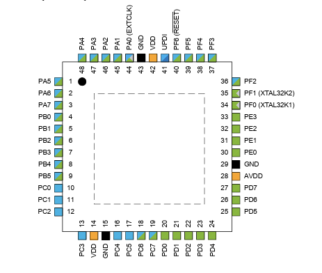
Pin Configuration and Descriptions

The AVR32DA48 comes in a 48-pin package. Below is a summary of the pin configuration:

Pin Number Pin Name Description
1 VDD Positive supply voltage
2 GND Ground
3 PA0 General-purpose I/O or ADC input
4 PA1 General-purpose I/O or ADC input
5 PB0 General-purpose I/O or PWM output
... ... ... (Refer to the datasheet for full details)
48 RESET Reset pin

For a complete pinout, refer to the official datasheet provided by Microchip.

Usage Instructions

How to Use the AVR32DA48 in a Circuit

  1. Power Supply: Connect the VDD pin to a stable power source (1.8V to 5.5V) and the GND pin to ground.
  2. Clock Configuration: Use an external crystal oscillator or the internal clock for timing. Configure the clock source in the firmware.
  3. GPIO Configuration: Set the GPIO pins as input or output in the firmware, depending on your application.
  4. Peripheral Initialization: Initialize the required peripherals (e.g., ADC, UART, SPI) in the firmware.
  5. Programming: Use a compatible programmer (e.g., Microchip MPLAB Snap or PICkit) to upload the firmware to the microcontroller.

Important Considerations and Best Practices

  • Decoupling Capacitors: Place decoupling capacitors (e.g., 0.1 µF) close to the VDD and GND pins to reduce noise.
  • Reset Pin: Connect a pull-up resistor (e.g., 10 kΩ) to the RESET pin to ensure proper operation.
  • Unused Pins: Configure unused pins as inputs with pull-up resistors or outputs to avoid floating states.
  • Debugging: Use the debug interface (e.g., UPDI) for troubleshooting and firmware debugging.

Example Code for Arduino UNO Integration

Although the AVR32DA48 is not directly compatible with Arduino UNO, it can communicate with it via UART. Below is an example of how to send data from the AVR32DA48 to an Arduino UNO:

AVR32DA48 Code (UART Transmission)

#include <avr/io.h>

// Initialize UART for communication
void UART_init(uint32_t baud_rate) {
    uint16_t ubrr = (F_CPU / (16 * baud_rate)) - 1; // Calculate UBRR value
    UBRR0H = (ubrr >> 8);  // Set high byte of UBRR
    UBRR0L = ubrr;         // Set low byte of UBRR
    UCSR0B = (1 << TXEN0); // Enable transmitter
    UCSR0C = (1 << UCSZ01) | (1 << UCSZ00); // Set frame: 8 data bits, 1 stop bit
}

// Transmit a single character
void UART_transmit(char data) {
    while (!(UCSR0A & (1 << UDRE0))); // Wait for empty transmit buffer
    UDR0 = data;                      // Load data into the buffer
}

// Main function
int main(void) {
    UART_init(9600); // Initialize UART with 9600 baud rate
    while (1) {
        UART_transmit('H'); // Transmit 'H'
        UART_transmit('i'); // Transmit 'i'
        UART_transmit('\n'); // Transmit newline
        _delay_ms(1000);     // Wait 1 second
    }
    return 0;
}

Arduino UNO Code (UART Reception)

void setup() {
    Serial.begin(9600); // Initialize Serial communication at 9600 baud
}

void loop() {
    if (Serial.available() > 0) { // Check if data is available
        char received = Serial.read(); // Read the received character
        Serial.print("Received: ");    // Print the received data
        Serial.println(received);
    }
}

Troubleshooting and FAQs

Common Issues and Solutions

  1. Microcontroller Not Responding

    • Cause: Incorrect power supply or missing decoupling capacitors.
    • Solution: Verify the power supply voltage and add decoupling capacitors near the VDD and GND pins.
  2. UART Communication Fails

    • Cause: Mismatched baud rates or incorrect wiring.
    • Solution: Ensure both devices use the same baud rate and check the TX/RX connections.
  3. Programmer Not Detecting the Microcontroller

    • Cause: Incorrect UPDI connection or missing pull-up resistor on the RESET pin.
    • Solution: Verify the UPDI pin connection and add a pull-up resistor to the RESET pin.
  4. ADC Readings Are Inaccurate

    • Cause: Noisy power supply or incorrect reference voltage.
    • Solution: Use a stable reference voltage and add filtering capacitors to the ADC input.

FAQs

  • Q: Can the AVR32DA48 operate at 5V?

    • A: Yes, the AVR32DA48 supports an operating voltage range of 1.8V to 5.5V.
  • Q: How do I program the AVR32DA48?

    • A: Use a compatible programmer, such as the Microchip MPLAB Snap or PICkit, and the UPDI interface.
  • Q: Does the AVR32DA48 support PWM?

    • A: Yes, the AVR32DA48 includes PWM functionality on specific GPIO pins.

For more details, refer to the official datasheet and application notes provided by Microchip Technology.