How to Use TCS230 color sensor: Examples, Pinouts, and Specs
Introduction
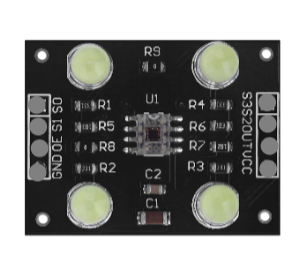
The TCS230 Color Sensor, manufactured by Kina (Part ID: TCS230), is a highly versatile and precise device designed to detect and measure the color of objects. It utilizes an array of photodiodes with integrated color filters to sense red, green, and blue light intensities. The sensor outputs a frequency signal proportional to the detected light intensity, making it easy to interface with microcontrollers and other digital systems.
Explore Projects Built with TCS230 color sensor

Explore Projects Built with TCS230 color sensor
Common Applications and Use Cases
- Color detection and sorting: Used in industrial automation for sorting objects by color.
- Robotics: Enables robots to recognize and respond to different colors.
- Consumer electronics: Integrated into devices for color calibration and recognition.
- Educational projects: Popular in DIY and Arduino-based projects for learning about color sensing.
Technical Specifications
The TCS230 color sensor is a robust and flexible component with the following key specifications:
| Parameter | Value |
|---|---|
| Supply Voltage (Vcc) | 2.7V to 5.5V |
| Operating Current | 2mA (typical) |
| Output Type | Square wave (frequency) |
| Output Frequency Range | 2 Hz to 500 kHz |
| Light Intensity Range | 0 to 100% |
| Temperature Range | -40°C to 85°C |
| Photodiode Array | 8x8 (64 photodiodes) |
| Color Filters | Red, Green, Blue, and Clear |
Pin Configuration and Descriptions
The TCS230 sensor module typically has an 8-pin configuration. Below is a detailed description of each pin:
| Pin | Name | Description |
|---|---|---|
| 1 | Vcc | Power supply input (2.7V to 5.5V). |
| 2 | GND | Ground connection. |
| 3 | S0 | Output frequency scaling selection input (see usage instructions). |
| 4 | S1 | Output frequency scaling selection input (see usage instructions). |
| 5 | S2 | Photodiode filter selection input (used to select red, green, blue, or clear). |
| 6 | S3 | Photodiode filter selection input (used to select red, green, blue, or clear). |
| 7 | OUT | Frequency output signal corresponding to light intensity. |
| 8 | OE | Output enable (active low). |
Usage Instructions
The TCS230 color sensor is straightforward to use in a circuit. Follow these steps to integrate it into your project:
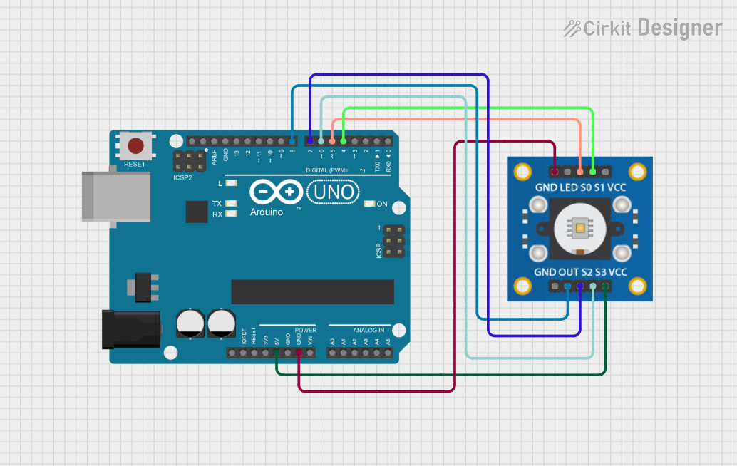
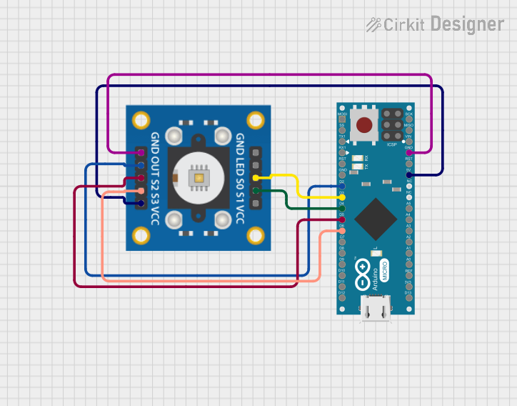
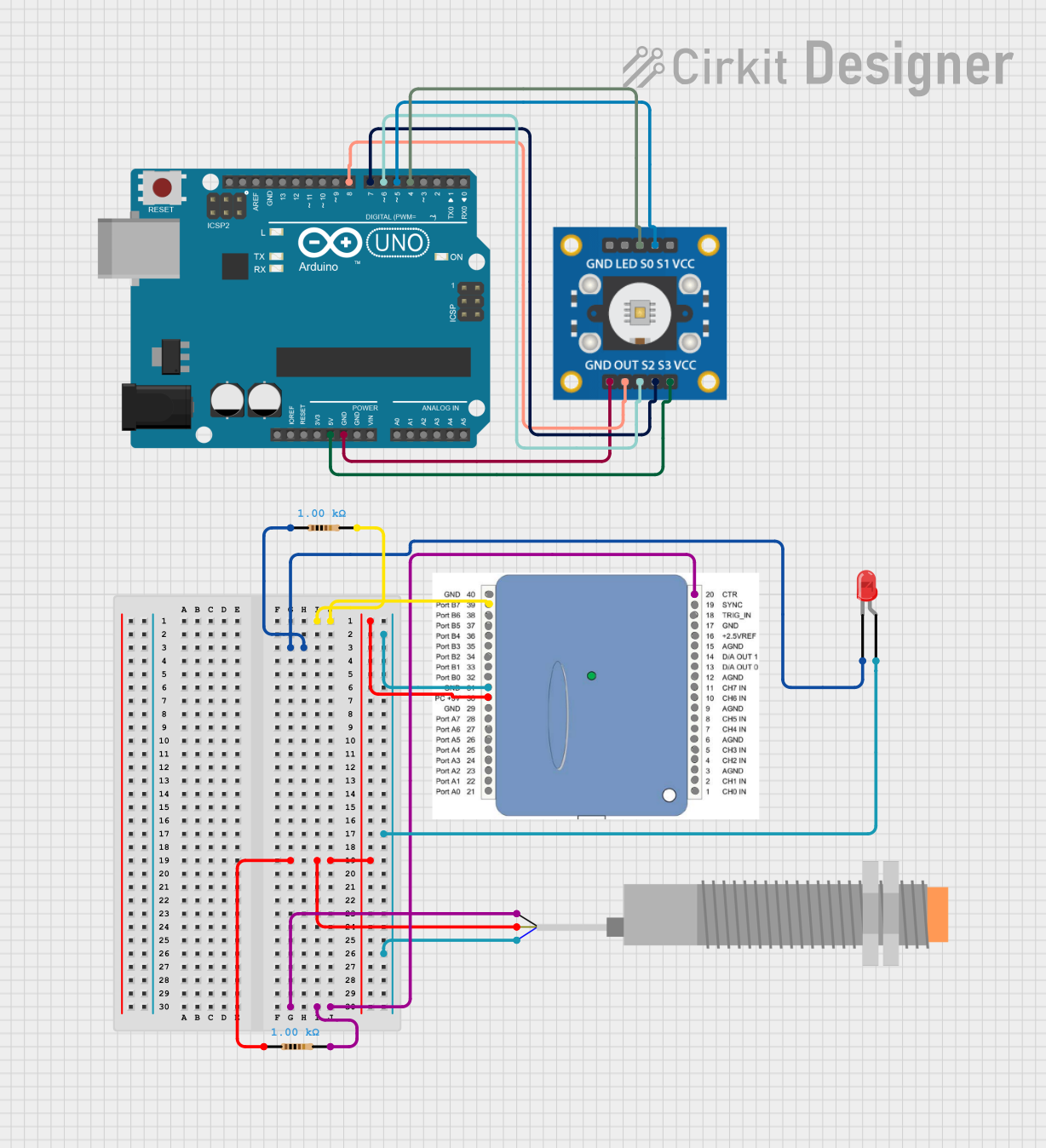
Connecting the TCS230 to a Microcontroller
- Power the sensor: Connect the Vcc pin to a 3.3V or 5V power source and the GND pin to ground.
- Set frequency scaling: Use the S0 and S1 pins to select the output frequency scaling factor:
- S0 = LOW, S1 = LOW: Power down mode.
- S0 = LOW, S1 = HIGH: 2% scaling.
- S0 = HIGH, S1 = LOW: 20% scaling.
- S0 = HIGH, S1 = HIGH: 100% scaling.
- Select color filter: Use the S2 and S3 pins to select the desired photodiode filter:
- S2 = LOW, S3 = LOW: Red filter.
- S2 = LOW, S3 = HIGH: Blue filter.
- S2 = HIGH, S3 = LOW: Clear (no filter).
- S2 = HIGH, S3 = HIGH: Green filter.
- Read the output: Connect the OUT pin to a digital input on your microcontroller to measure the frequency signal.
Example: Using the TCS230 with Arduino UNO
Below is an example Arduino sketch to read RGB values from the TCS230 sensor:
// Define TCS230 pins
#define S0 4  // Frequency scaling pin S0
#define S1 5  // Frequency scaling pin S1
#define S2 6  // Color filter selection pin S2
#define S3 7  // Color filter selection pin S3
#define OUT 8 // Frequency output pin

void setup() {
  // Set pin modes
  pinMode(S0, OUTPUT);
  pinMode(S1, OUTPUT);
  pinMode(S2, OUTPUT);
  pinMode(S3, OUTPUT);
  pinMode(OUT, INPUT);

  // Set frequency scaling to 20%
  digitalWrite(S0, HIGH);
  digitalWrite(S1, LOW);

  Serial.begin(9600); // Initialize serial communication
}

void loop() {
  int red, green, blue;

  // Measure red light intensity
  digitalWrite(S2, LOW);
  digitalWrite(S3, LOW);
  red = pulseIn(OUT, LOW); // Measure frequency for red

  // Measure green light intensity
  digitalWrite(S2, HIGH);
  digitalWrite(S3, HIGH);
  green = pulseIn(OUT, LOW); // Measure frequency for green

  // Measure blue light intensity
  digitalWrite(S2, LOW);
  digitalWrite(S3, HIGH);
  blue = pulseIn(OUT, LOW); // Measure frequency for blue

  // Print RGB values
  Serial.print("Red: ");
  Serial.print(red);
  Serial.print(" Green: ");
  Serial.print(green);
  Serial.print(" Blue: ");
  Serial.println(blue);

  delay(500); // Wait before next reading
}
Important Considerations and Best Practices
- Ambient light: Minimize ambient light interference by enclosing the sensor or using it in controlled lighting conditions.
- Frequency scaling: Use the appropriate scaling factor (S0, S1) to match the sensor's output frequency to your microcontroller's input capabilities.
- Calibration: Calibrate the sensor for your specific application to ensure accurate color detection.
Troubleshooting and FAQs
Common Issues and Solutions
No output signal from the sensor:
- Ensure the sensor is powered correctly (check Vcc and GND connections).
- Verify that the OE pin is set to LOW (active).
Incorrect color readings:
- Check the S2 and S3 pin configurations for proper filter selection.
- Ensure the sensor is not exposed to excessive ambient light.
Output frequency too high or too low:
- Adjust the frequency scaling using the S0 and S1 pins.
Arduino not detecting frequency:
- Verify the OUT pin connection to the correct Arduino digital input pin.
- Ensure the Arduino's pulseIn function is used correctly.
FAQs
Q: Can the TCS230 detect colors in low light conditions?
A: Yes, but the sensor's accuracy may decrease. Use an external light source for better results.
Q: How do I improve the accuracy of color detection?
A: Calibrate the sensor for your specific environment and application. Minimize ambient light interference.
Q: Can the TCS230 detect colors on moving objects?
A: Yes, but ensure the object moves slowly enough for the sensor to capture accurate readings.
Q: Is the TCS230 compatible with 3.3V systems?
A: Yes, the sensor operates with a supply voltage range of 2.7V to 5.5V, making it compatible with both 3.3V and 5V systems.