How to Use Analog Piezo Vibration Sensor Module: Examples, Pinouts, and Specs
Introduction
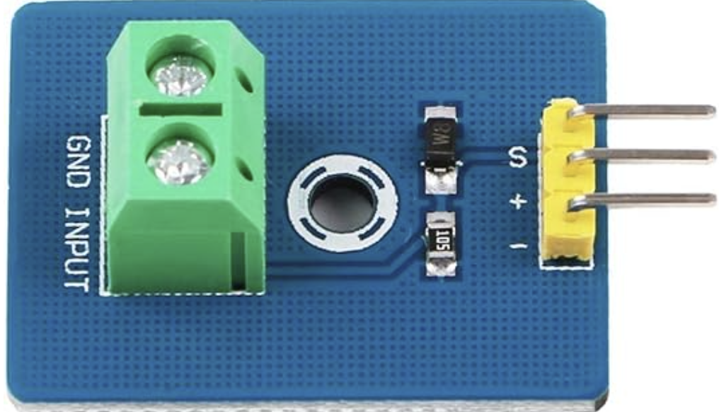
The Analog Piezo Vibration Sensor Module by DollaTek (Part ID: B081JNCYGL) is a versatile sensor designed to detect vibrations and convert them into an analog voltage signal. This module is ideal for applications requiring motion detection, impact sensing, or vibration monitoring. It is commonly used in projects such as security systems, industrial equipment monitoring, and interactive electronics.
The sensor operates by utilizing a piezoelectric element that generates a voltage when subjected to mechanical stress or vibrations. This voltage is then output as an analog signal, which can be read by microcontrollers or other electronic systems.
Explore Projects Built with Analog Piezo Vibration Sensor Module
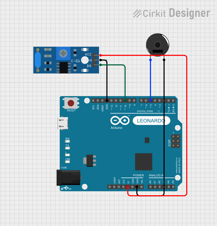
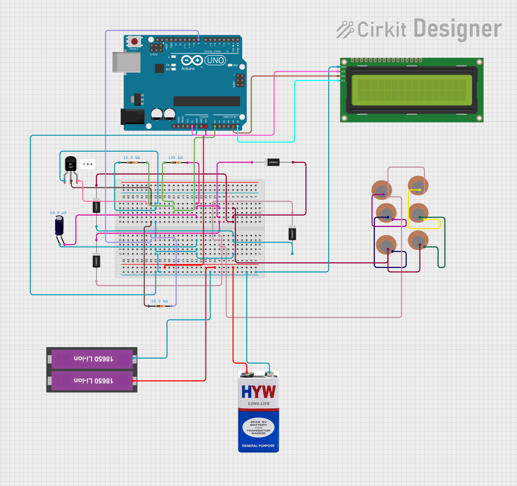
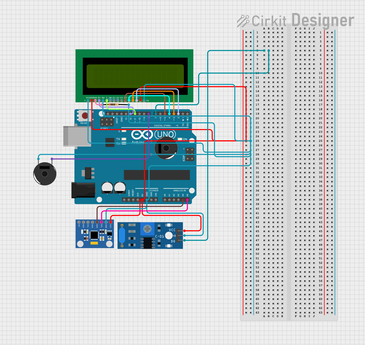
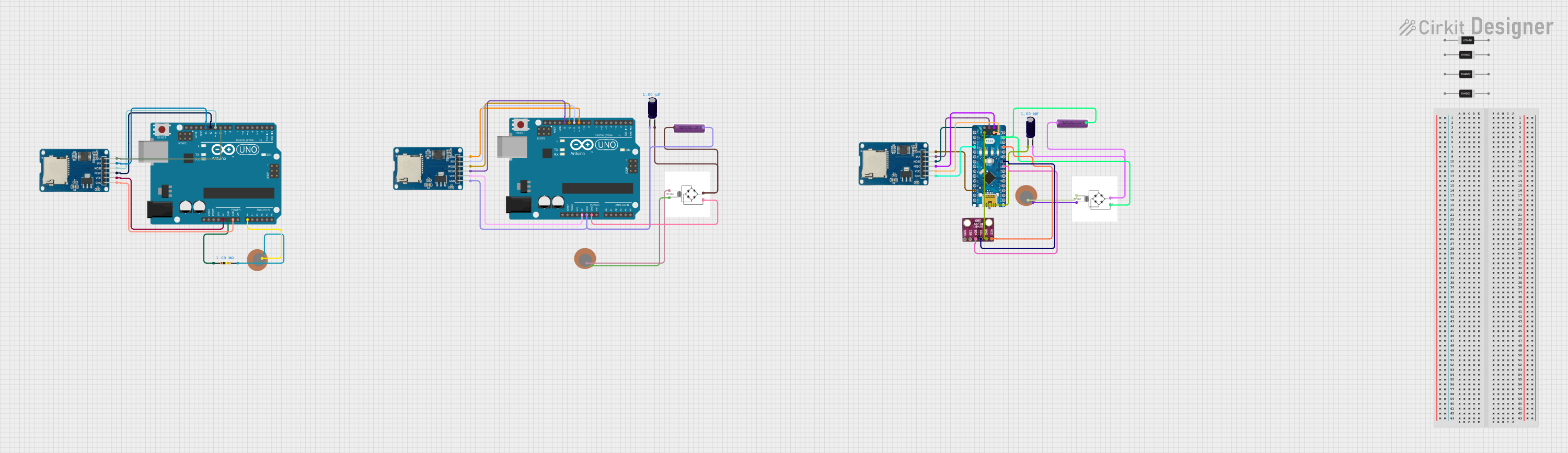
Explore Projects Built with Analog Piezo Vibration Sensor Module
Technical Specifications
Below are the key technical details of the Analog Piezo Vibration Sensor Module:
| Parameter | Specification |
|---|---|
| Manufacturer | DollaTek |
| Part ID | B081JNCYGL |
| Operating Voltage | 3.3V to 5V DC |
| Output Signal | Analog voltage |
| Sensitivity | Adjustable via onboard potentiometer |
| Dimensions | 32mm x 17mm x 8mm |
| Operating Temperature | -20°C to 70°C |
| Interface Type | 3-pin (VCC, GND, Signal) |
Pin Configuration and Descriptions
The module has a 3-pin interface for easy integration into circuits. Below is the pin configuration:
| Pin | Name | Description |
|---|---|---|
| 1 | VCC | Power supply pin. Connect to 3.3V or 5V DC. |
| 2 | GND | Ground pin. Connect to the ground of the circuit. |
| 3 | Signal | Analog output pin. Outputs a voltage proportional to the detected vibration. |
Usage Instructions
How to Use the Component in a Circuit
- Power the Module: Connect the
VCCpin to a 3.3V or 5V DC power source and theGNDpin to the ground of your circuit. - Connect the Signal Pin: Connect the
Signalpin to an analog input pin of your microcontroller (e.g., Arduino UNO). - Adjust Sensitivity: Use the onboard potentiometer to adjust the sensitivity of the sensor. Turning the potentiometer clockwise increases sensitivity, while turning it counterclockwise decreases it.
- Read the Output: The module outputs an analog voltage signal that corresponds to the intensity of the detected vibration. This signal can be read and processed by a microcontroller.
Important Considerations and Best Practices
- Power Supply: Ensure the module is powered within its operating voltage range (3.3V to 5V DC). Exceeding this range may damage the sensor.
- Signal Noise: The output signal may contain noise due to environmental factors. Use appropriate filtering techniques in your circuit or software to improve signal quality.
- Mounting: Secure the module firmly to avoid false readings caused by unintended vibrations.
- Calibration: Adjust the sensitivity using the potentiometer to suit your specific application.
Example: Connecting to an Arduino UNO
Below is an example of how to connect and use the Analog Piezo Vibration Sensor Module with an Arduino UNO:
Circuit Connections
- Connect the
VCCpin of the sensor to the 5V pin on the Arduino. - Connect the
GNDpin of the sensor to the GND pin on the Arduino. - Connect the
Signalpin of the sensor to the A0 analog input pin on the Arduino.
Arduino Code
// Analog Piezo Vibration Sensor Module Example
// Reads the analog signal from the sensor and prints it to the Serial Monitor.

const int sensorPin = A0; // Define the analog pin connected to the sensor
int sensorValue = 0;      // Variable to store the sensor reading

void setup() {
  Serial.begin(9600); // Initialize serial communication at 9600 baud
}

void loop() {
  sensorValue = analogRead(sensorPin); // Read the analog value from the sensor
  Serial.print("Vibration Level: ");  // Print a label for the output
  Serial.println(sensorValue);        // Print the sensor value to the Serial Monitor
  delay(100);                         // Add a short delay for readability
}
Output
When the sensor detects vibrations, the analog value read by the Arduino will increase. The Serial Monitor will display the vibration level in real-time.
Troubleshooting and FAQs
Common Issues and Solutions
No Output Signal
- Cause: The module is not powered correctly.
- Solution: Verify that the
VCCandGNDpins are connected properly and that the power supply voltage is within the specified range.
Inconsistent Readings
- Cause: Environmental noise or loose connections.
- Solution: Ensure the module is securely mounted and use software or hardware filtering to reduce noise.
Low Sensitivity
- Cause: The potentiometer is not adjusted correctly.
- Solution: Turn the potentiometer clockwise to increase sensitivity.
High Sensitivity Leading to False Triggers
- Cause: The potentiometer is set too high.
- Solution: Turn the potentiometer counterclockwise to decrease sensitivity.
FAQs
Q: Can this module detect very small vibrations?
A: Yes, the sensitivity can be adjusted using the onboard potentiometer to detect small vibrations.
Q: Is this module compatible with 3.3V microcontrollers like ESP32?
A: Yes, the module operates at 3.3V to 5V, making it compatible with both 3.3V and 5V systems.
Q: How can I filter noise from the output signal?
A: You can use a low-pass filter circuit or implement software-based filtering techniques to reduce noise.
Q: Can this module be used outdoors?
A: The module is not weatherproof. If used outdoors, it should be enclosed in a protective casing to prevent damage from moisture or dust.