
How to Use mlx90614: Examples, Pinouts, and Specs
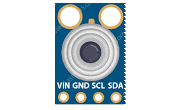
 Design with mlx90614 in Cirkit Designer
Introduction
The MLX90614 is a highly accurate, non-contact infrared temperature sensor designed to measure the temperature of objects without requiring physical contact. Manufactured by Melexis, this sensor uses infrared radiation to determine the temperature of an object and communicates the data via the I2C protocol. Its compact design and ease of use make it ideal for a wide range of applications.
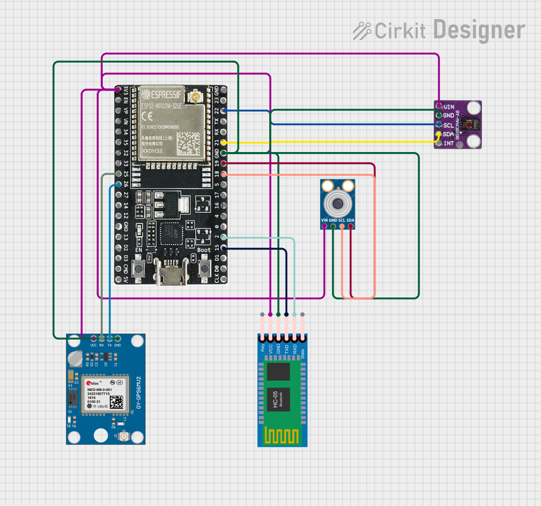
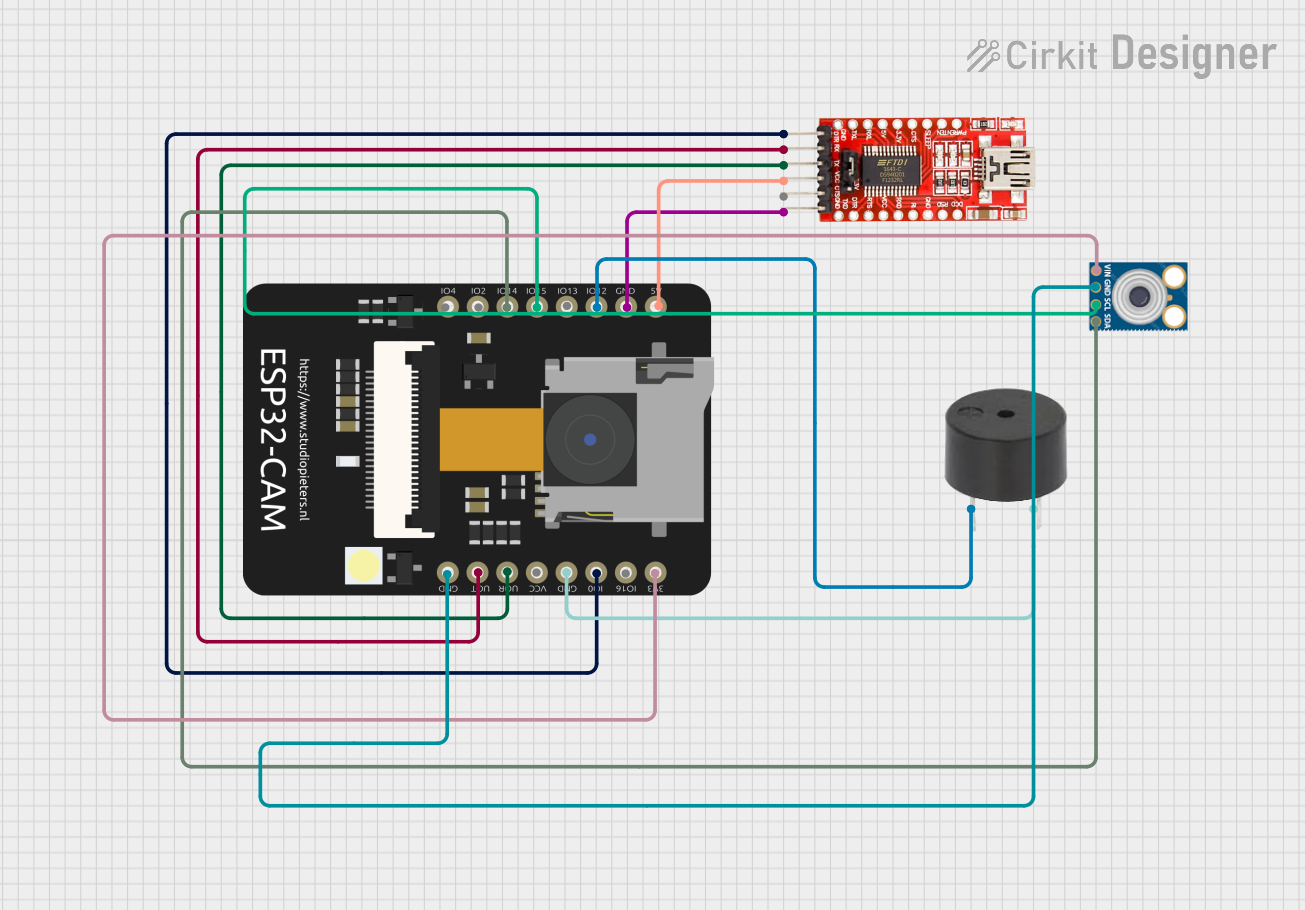
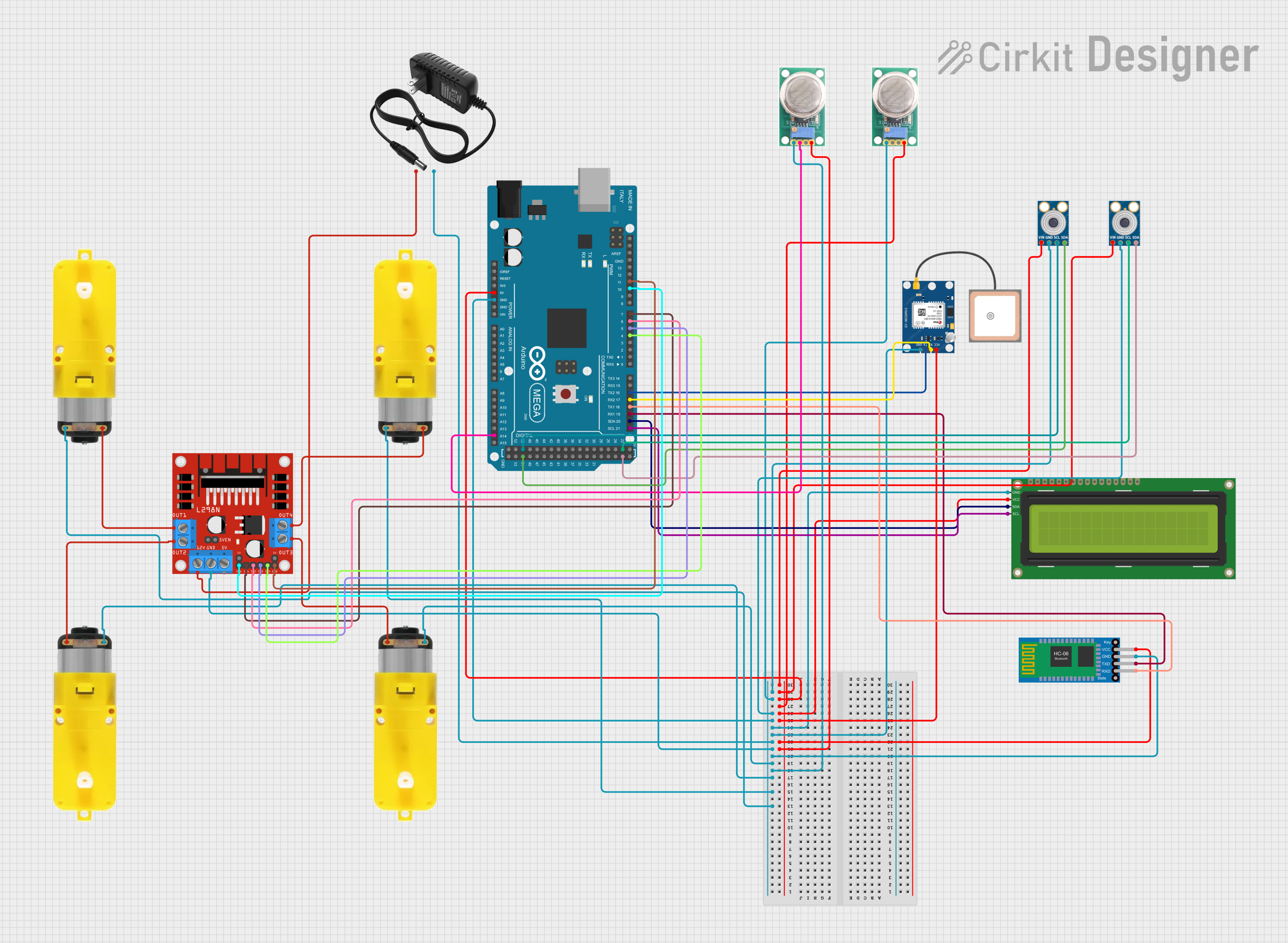
Explore Projects Built with mlx90614
 Open Project in Cirkit Designer
 Open Project in Cirkit Designer
 Open Project in Cirkit Designer
 Open Project in Cirkit Designer
Explore Projects Built with mlx90614
Open Project in Cirkit DesignerOpen Project in Cirkit DesignerOpen Project in Cirkit DesignerOpen Project in Cirkit DesignerCommon Applications and Use Cases
- Non-contact temperature measurement in industrial and medical settings
- Thermal imaging systems
- HVAC (Heating, Ventilation, and Air Conditioning) monitoring
- Consumer electronics, such as smart thermostats
- Automotive climate control systems
- Wearable devices for health monitoring
Technical Specifications
The MLX90614 is available in various models, but the following are the general specifications for the most commonly used version:
| Parameter | Value |
|---|---|
| Operating Voltage | 3.6V to 5V |
| Communication Protocol | I2C and PWM |
| Temperature Range (Object) | -70°C to +380°C |
| Temperature Range (Ambient) | -40°C to +125°C |
| Accuracy | ±0.5°C (typical, for 0°C to +50°C range) |
| Field of View (FOV) | 35° |
| Resolution | 0.02°C |
| Current Consumption | 1.5mA (typical) |
| Dimensions | 8mm x 8mm x 5mm (TO-39 package) |
Pin Configuration and Descriptions
The MLX90614 typically comes in a 4-pin TO-39 package. Below is the pinout:
| Pin Number | Pin Name | Description |
|---|---|---|
| 1 | VDD | Power supply (3.6V to 5V) |
| 2 | VSS | Ground |
| 3 | SDA | I2C data line |
| 4 | SCL | I2C clock line |
Usage Instructions
How to Use the MLX90614 in a Circuit
- Power Supply: Connect the VDD pin to a 3.6V to 5V power source and the VSS pin to ground.
- I2C Communication: Connect the SDA and SCL pins to the corresponding I2C pins on your microcontroller. Use pull-up resistors (typically 4.7kΩ) on both SDA and SCL lines.
- Addressing: The default I2C address of the MLX90614 is
0x5A. Ensure no other devices on the I2C bus share this address, or reconfigure the address if necessary. - Bypass Capacitor: Place a 0.1µF decoupling capacitor between VDD and VSS to stabilize the power supply.
Important Considerations and Best Practices
- Avoid exposing the sensor to direct sunlight or strong infrared sources, as this may affect accuracy.
- Ensure the sensor is mounted securely and aligned properly for accurate temperature readings.
- Use proper shielding and grounding to minimize electrical noise in the circuit.
- If using the PWM output mode, ensure your microcontroller can read the PWM signal accurately.
Example: Using the MLX90614 with Arduino UNO
Below is an example of how to interface the MLX90614 with an Arduino UNO using the I2C protocol. This example uses the Adafruit MLX90614 library.
Wiring Diagram
| MLX90614 Pin | Arduino UNO Pin |
|---|---|
| VDD | 5V |
| VSS | GND |
| SDA | A4 |
| SCL | A5 |
Arduino Code
#include <Wire.h>
#include <Adafruit_MLX90614.h>

// Create an instance of the MLX90614 library
Adafruit_MLX90614 mlx = Adafruit_MLX90614();

void setup() {
  Serial.begin(9600); // Initialize serial communication at 9600 baud
  if (!mlx.begin()) {
    Serial.println("Error: MLX90614 not detected. Check wiring!");
    while (1); // Halt execution if sensor initialization fails
  }
  Serial.println("MLX90614 initialized successfully!");
}

void loop() {
  // Read object and ambient temperatures
  double objectTemp = mlx.readObjectTempC();
  double ambientTemp = mlx.readAmbientTempC();

  // Print the temperatures to the Serial Monitor
  Serial.print("Object Temperature: ");
  Serial.print(objectTemp);
  Serial.println(" °C");

  Serial.print("Ambient Temperature: ");
  Serial.print(ambientTemp);
  Serial.println(" °C");

  delay(1000); // Wait 1 second before the next reading
}
Troubleshooting and FAQs
Common Issues and Solutions
Sensor Not Detected
- Cause: Incorrect wiring or I2C address conflict.
- Solution: Double-check the wiring and ensure the SDA and SCL lines are connected properly. Verify that no other devices on the I2C bus share the same address.
Inaccurate Temperature Readings
- Cause: Sensor exposed to strong infrared sources or misaligned.
- Solution: Shield the sensor from direct sunlight or strong IR sources. Ensure the sensor is properly aligned with the target object.
No Data on Serial Monitor
- Cause: Incorrect baud rate or sensor initialization failure.
- Solution: Ensure the Serial Monitor is set to the correct baud rate (9600 in the example). Check the wiring and power supply.
FAQs
Can the MLX90614 measure the temperature of liquids?
- Yes, but ensure the sensor is not exposed to splashes or condensation. The liquid's surface must be visible to the sensor.
What is the maximum distance for accurate measurements?
- The effective range depends on the size of the object and its emissivity. For small objects, the sensor should be closer, while larger objects can be measured from farther away.
Can I use multiple MLX90614 sensors on the same I2C bus?
- Yes, but you must configure each sensor with a unique I2C address. This can be done by reprogramming the sensor's EEPROM.
By following this documentation, you can effectively integrate the MLX90614 into your projects and troubleshoot common issues.