How to Use NPK Sensor: Examples, Pinouts, and Specs
Introduction
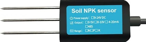
The NPK Sensor (Manufacturer: DFRobot, Part ID: NPK) is a specialized electronic component designed to measure the levels of nitrogen (N), phosphorus (P), and potassium (K) in soil. These three nutrients are critical for plant growth, and the sensor provides real-time data to help users assess soil fertility and optimize agricultural practices.
This sensor is widely used in applications such as:
- Precision agriculture and smart farming
- Soil quality monitoring
- Research and development in agronomy
- Gardening and horticulture
By integrating the NPK Sensor into a monitoring system, users can make informed decisions about fertilization and crop management, leading to improved yields and reduced environmental impact.
Explore Projects Built with NPK Sensor
Explore Projects Built with NPK Sensor
Technical Specifications
The following table outlines the key technical details of the DFRobot NPK Sensor:
| Parameter | Specification |
|---|---|
| Operating Voltage | 5V DC |
| Operating Current | ≤ 50mA |
| Measurement Range | 0–1999 mg/kg (ppm) for N, P, and K |
| Communication Protocol | UART (9600 bps default baud rate) |
| Operating Temperature | -20°C to 60°C |
| Waterproof Rating | IP68 |
| Cable Length | 1.5 meters |
Pin Configuration and Descriptions
The NPK Sensor has a 4-pin interface for communication and power. The pinout is as follows:
| Pin | Name | Description |
|---|---|---|
| 1 | VCC | Power supply input (5V DC) |
| 2 | GND | Ground connection |
| 3 | RX | UART Receive pin (connect to TX of microcontroller) |
| 4 | TX | UART Transmit pin (connect to RX of microcontroller) |
Usage Instructions
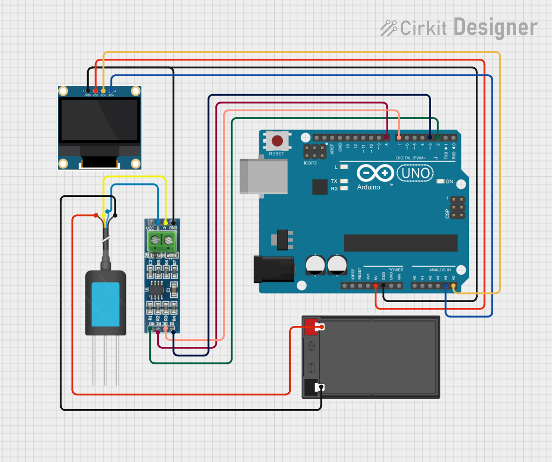
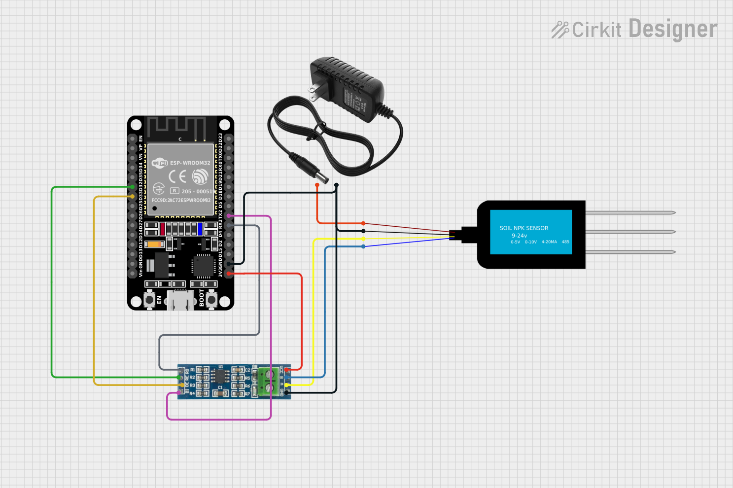
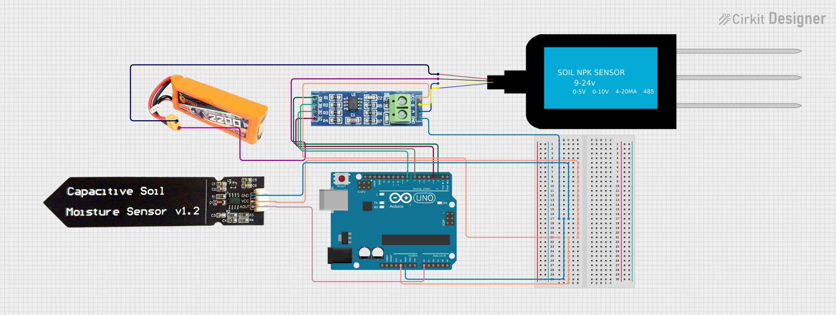
How to Use the NPK Sensor in a Circuit
- Power the Sensor: Connect the VCC pin to a 5V DC power source and the GND pin to ground.
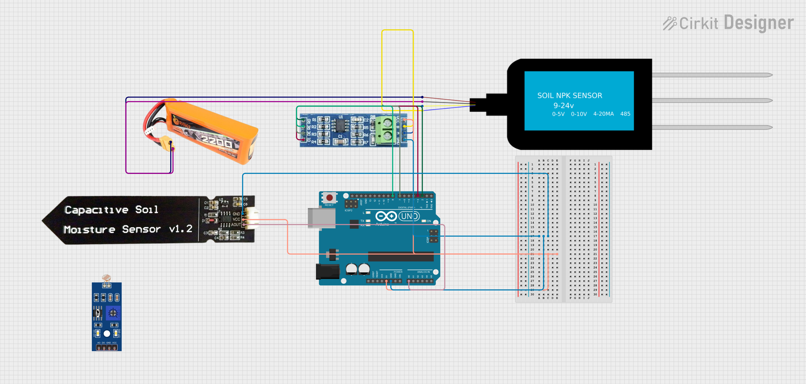
- Connect to a Microcontroller: Use the RX and TX pins to establish UART communication with a microcontroller (e.g., Arduino UNO).
- Place the Sensor in Soil: Insert the sensor probe into the soil at the desired depth. Ensure the probe is fully in contact with the soil for accurate readings.
- Read Data: Use the microcontroller to send commands and receive data from the sensor. The sensor outputs N, P, and K values in mg/kg (ppm).
Important Considerations and Best Practices
- Soil Preparation: Ensure the soil is moist but not waterlogged for accurate readings. Dry or overly wet soil may affect the sensor's performance.
- Calibration: The sensor is factory-calibrated, but periodic calibration may be required for high-precision applications.
- Avoid Damage: Do not bend or apply excessive force to the probe. Handle the sensor carefully to avoid damaging the internal components.
- Power Supply: Use a stable 5V DC power source to prevent communication errors or inaccurate readings.
Example Code for Arduino UNO
Below is an example of how to interface the NPK Sensor with an Arduino UNO:
#include <SoftwareSerial.h>

// Define RX and TX pins for SoftwareSerial
SoftwareSerial npkSerial(10, 11); // RX = pin 10, TX = pin 11

void setup() {
  Serial.begin(9600); // Initialize Serial Monitor
  npkSerial.begin(9600); // Initialize NPK Sensor communication

  Serial.println("NPK Sensor Initialized");
}

void loop() {
  if (npkSerial.available()) {
    // Read data from the NPK Sensor
    String npkData = "";
    while (npkSerial.available()) {
      char c = npkSerial.read();
      npkData += c;
    }

    // Print the received data to the Serial Monitor
    Serial.println("NPK Sensor Data: " + npkData);
  }

  delay(1000); // Wait 1 second before the next reading
}
Note: Ensure the RX and TX pins of the sensor are correctly connected to the TX and RX pins of the Arduino UNO, respectively. Use a logic level shifter if the Arduino operates at 3.3V logic levels.
Troubleshooting and FAQs
Common Issues and Solutions
No Data Received from the Sensor
- Cause: Incorrect wiring or loose connections.
- Solution: Double-check the connections, ensuring RX and TX pins are correctly connected to the microcontroller.
Inaccurate Readings
- Cause: Soil is too dry, too wet, or contains debris.
- Solution: Ensure the soil is moist and free of large debris. Recalibrate the sensor if necessary.
Communication Errors
- Cause: Incorrect baud rate or power supply issues.
- Solution: Verify that the UART baud rate is set to 9600 bps. Use a stable 5V DC power source.
Sensor Not Responding
- Cause: Damaged probe or sensor.
- Solution: Inspect the probe for physical damage. Replace the sensor if necessary.
FAQs
Q1: Can the NPK Sensor be used in hydroponic systems?
A1: No, the NPK Sensor is designed for soil-based measurements and is not suitable for liquid environments.
Q2: How often should the sensor be calibrated?
A2: The sensor is factory-calibrated, but calibration is recommended every 6–12 months for high-precision applications.
Q3: Is the sensor compatible with 3.3V microcontrollers?
A3: The sensor operates at 5V. Use a logic level shifter to interface with 3.3V microcontrollers.
Q4: Can the sensor be left in the soil permanently?
A4: Yes, the sensor is waterproof (IP68) and can be left in the soil for long-term monitoring. However, periodic maintenance is recommended.
This documentation provides a comprehensive guide to using the DFRobot NPK Sensor effectively. For further assistance, refer to the manufacturer's datasheet or support resources.