How to Use Line Following (sensor board): Examples, Pinouts, and Specs
Introduction
The Line Following Sensor Board is a specialized electronic module designed to detect and follow lines on the ground. It is commonly used in robotics for navigation and path tracking, enabling robots to autonomously follow predefined paths. The board typically consists of multiple infrared (IR) sensors that detect the contrast between a line (usually black) and the surrounding surface (usually white or light-colored).
Explore Projects Built with Line Following (sensor board)

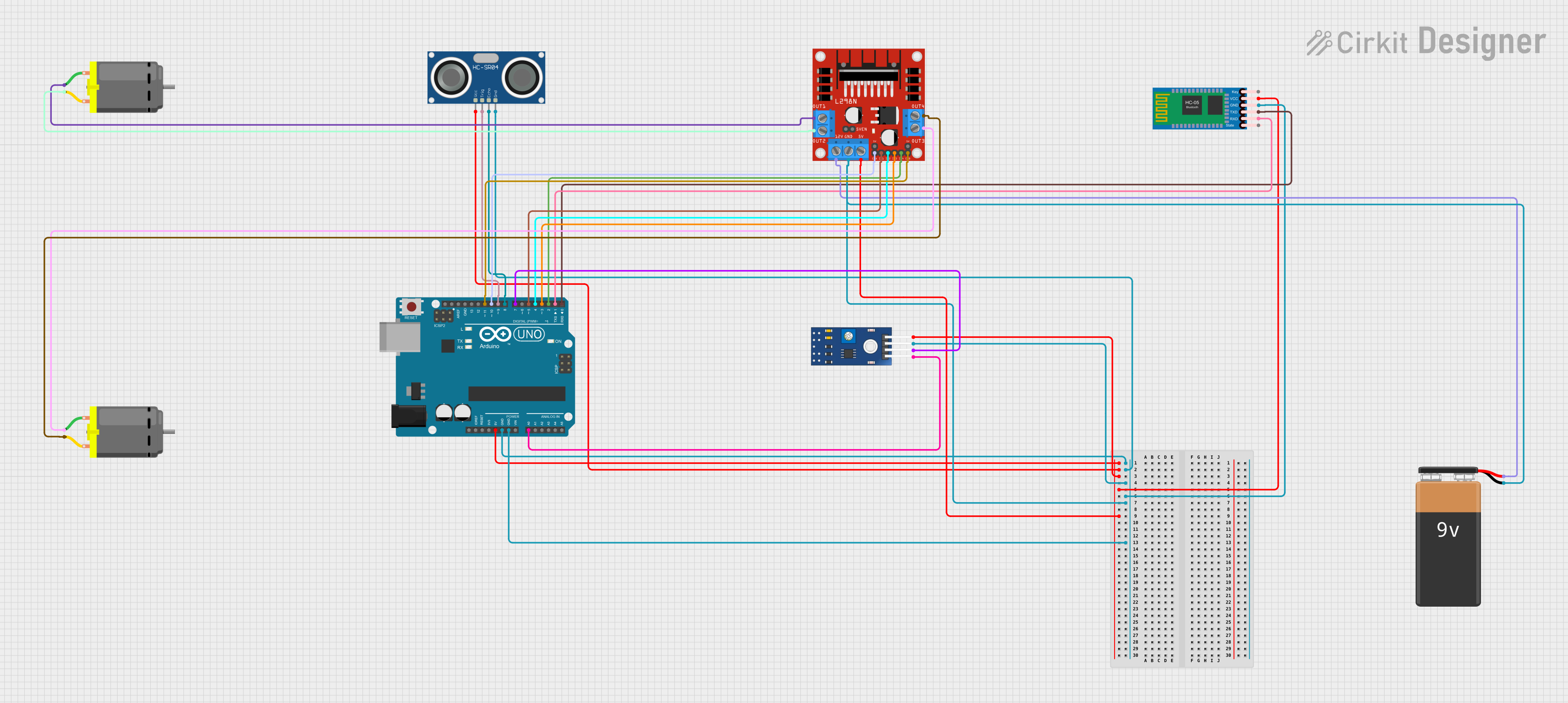
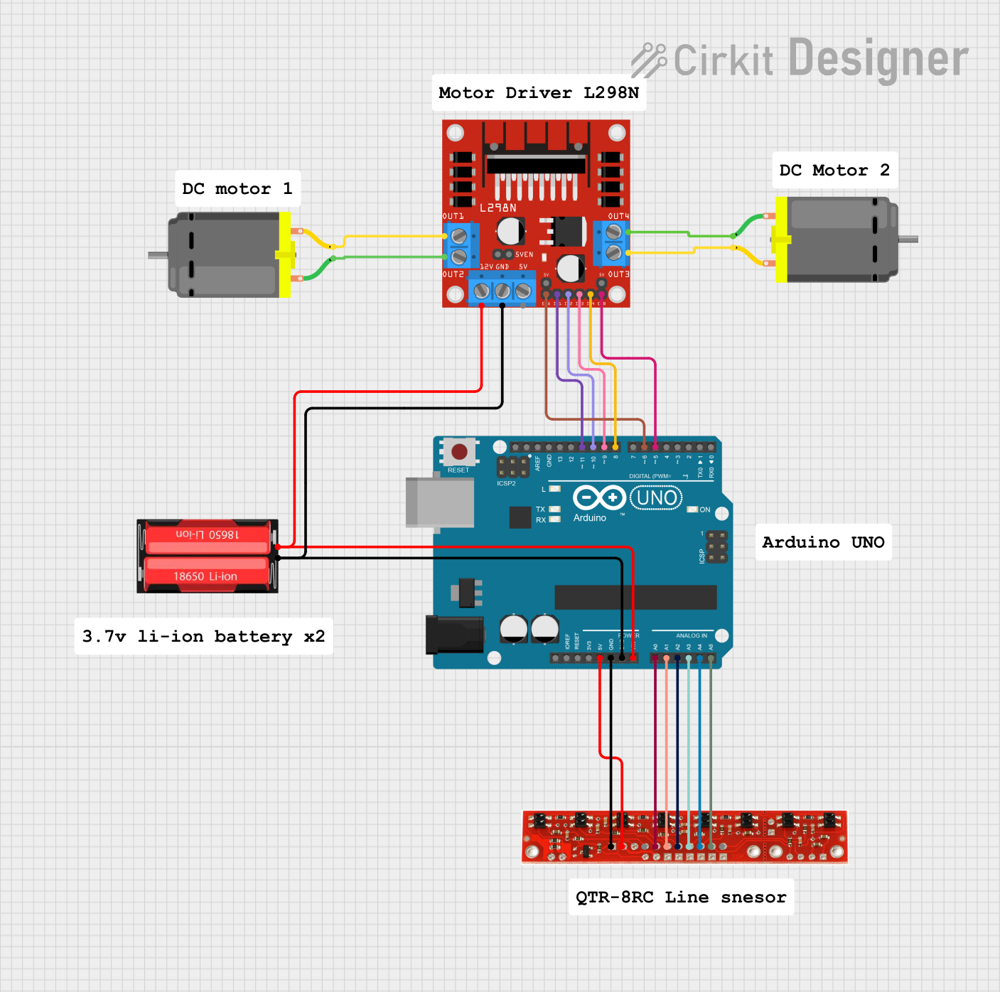
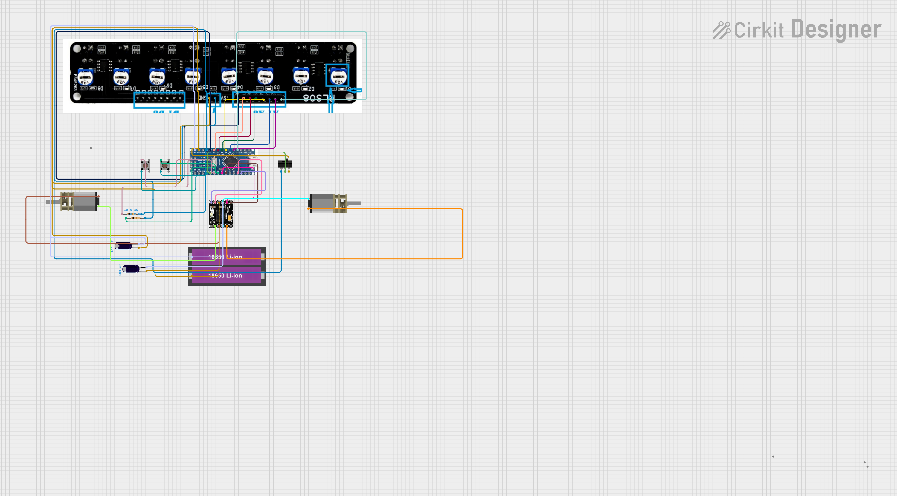
Explore Projects Built with Line Following (sensor board)
Common Applications and Use Cases
- Autonomous robots for line-following competitions
- Industrial automation for guided vehicles
- Educational robotics projects
- Path tracking in delivery robots
Technical Specifications
The following table outlines the key technical details of the Line Following Sensor Board:
| Parameter | Value |
|---|---|
| Operating Voltage | 3.3V to 5V |
| Operating Current | 10mA to 50mA (depending on usage) |
| Detection Range | 2mm to 10mm above the surface |
| Sensor Type | Infrared (IR) photodiodes |
| Output Type | Digital (High/Low) or Analog |
| Dimensions | Varies by model (e.g., 70mm x 20mm) |
| Number of Sensors | Typically 3 to 8 IR sensors |
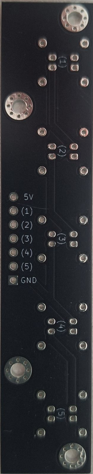
Pin Configuration and Descriptions
The pinout of the Line Following Sensor Board may vary slightly depending on the model, but a typical configuration is as follows:
| Pin Name | Description |
|---|---|
| VCC | Power supply input (3.3V to 5V) |
| GND | Ground connection |
| OUT1, OUT2... | Digital or analog outputs from individual sensors (e.g., OUT1 for Sensor 1) |
| EN | Enable pin (optional, used to activate or deactivate the board) |
Usage Instructions
How to Use the Component in a Circuit
- Power the Board: Connect the
VCCpin to a 3.3V or 5V power source and theGNDpin to the ground of your circuit. - Connect Outputs: Connect the output pins (
OUT1,OUT2, etc.) to the input pins of your microcontroller or motor driver. These outputs indicate whether the corresponding sensor detects a line. - Position the Board: Mount the sensor board on your robot, ensuring the IR sensors face the ground and are positioned 2mm to 10mm above the surface.
- Calibrate the Sensors: Adjust the sensitivity of the sensors (if adjustable) to ensure accurate detection of the line.
Important Considerations and Best Practices
- Surface Contrast: Ensure the line has a high contrast with the surrounding surface (e.g., black line on a white floor).
- Ambient Light: Minimize ambient light interference, as it can affect the IR sensors' performance.
- Speed Adjustment: If used in a robot, adjust the robot's speed to allow the sensors sufficient time to detect the line and make corrections.
- Testing: Test the sensor board on the intended surface before deployment to ensure reliable operation.
Example Code for Arduino UNO
Below is an example of how to use a Line Following Sensor Board with an Arduino UNO:
// Line Following Sensor Board Example Code
// This code reads the digital outputs of a 3-sensor board and prints the results
// to the Serial Monitor. Adjust pin numbers as per your board's configuration.

#define SENSOR_LEFT 2   // Pin connected to the left sensor output
#define SENSOR_CENTER 3 // Pin connected to the center sensor output
#define SENSOR_RIGHT 4  // Pin connected to the right sensor output

void setup() {
  pinMode(SENSOR_LEFT, INPUT);   // Set left sensor pin as input
  pinMode(SENSOR_CENTER, INPUT); // Set center sensor pin as input
  pinMode(SENSOR_RIGHT, INPUT);  // Set right sensor pin as input
  Serial.begin(9600);            // Initialize serial communication
}

void loop() {
  // Read sensor values
  int left = digitalRead(SENSOR_LEFT);
  int center = digitalRead(SENSOR_CENTER);
  int right = digitalRead(SENSOR_RIGHT);

  // Print sensor values to Serial Monitor
  Serial.print("Left: ");
  Serial.print(left);
  Serial.print(" | Center: ");
  Serial.print(center);
  Serial.print(" | Right: ");
  Serial.println(right);

  delay(100); // Small delay for readability
}
Troubleshooting and FAQs
Common Issues Users Might Face
Sensors Not Detecting the Line:
- Cause: Insufficient contrast between the line and the surface.
- Solution: Use a darker line or a lighter surface to improve contrast.
Inconsistent Readings:
- Cause: Ambient light interference or incorrect sensor height.
- Solution: Shield the sensors from ambient light and ensure the board is positioned at the correct height (2mm to 10mm).
Robot Veering Off the Line:
- Cause: Incorrect sensor calibration or improper motor control.
- Solution: Recalibrate the sensors and adjust the motor control logic in your code.
No Output from Sensors:
- Cause: Incorrect wiring or insufficient power supply.
- Solution: Double-check the wiring and ensure the board is receiving the correct voltage.
Solutions and Tips for Troubleshooting
- Check Connections: Ensure all pins are securely connected to the microcontroller or power source.
- Test Individual Sensors: Test each sensor output individually to identify faulty sensors.
- Use a Multimeter: Measure the voltage at the output pins to verify sensor functionality.
- Update Code: Ensure your microcontroller code matches the pin configuration of the sensor board.
By following this documentation, you can effectively integrate and troubleshoot the Line Following Sensor Board in your robotics projects.