How to Use PIR Sensor: Examples, Pinouts, and Specs
Introduction
A Passive Infrared (PIR) Sensor detects motion by measuring changes in infrared radiation, typically emitted by warm bodies. It is a widely used component in motion detection systems due to its low cost, low power consumption, and ease of integration. PIR sensors are commonly found in security systems, automatic lighting, and home automation projects.
Explore Projects Built with PIR Sensor
Explore Projects Built with PIR Sensor
Common Applications and Use Cases
- Motion-activated lighting systems
- Intruder detection in security systems
- Automatic doors and entry systems
- Smart home automation
- Energy-saving systems in offices and homes
Technical Specifications
Below are the key technical details of a standard PIR sensor module:
| Parameter | Value |
|---|---|
| Operating Voltage | 4.5V to 20V DC |
| Current Consumption | < 50 µA (standby), ~65 mA (active) |
| Detection Range | 3 to 7 meters (adjustable) |
| Detection Angle | ~120° (varies by model) |
| Output Signal | Digital (High: 3.3V or 5V, Low: 0V) |
| Warm-up Time | ~30 seconds |
| Operating Temperature | -20°C to 50°C |
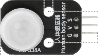
Pin Configuration and Descriptions
The PIR sensor module typically has three pins:
| Pin | Name | Description |
|---|---|---|
| 1 | VCC | Power supply input (4.5V to 20V DC) |
| 2 | OUT | Digital output pin (High when motion is detected) |
| 3 | GND | Ground connection |
Some PIR modules may also include adjustable potentiometers for:
- Sensitivity: Adjusts the detection range.
- Time Delay: Sets the duration for which the output remains HIGH after motion is detected.
Usage Instructions
How to Use the PIR Sensor in a Circuit
- Power the Sensor: Connect the VCC pin to a 5V power source and the GND pin to ground.
- Connect the Output: Connect the OUT pin to a microcontroller's digital input pin or directly to an external device (e.g., a relay or LED).
- Adjust Settings: Use the onboard potentiometers to fine-tune the sensitivity and time delay as per your application.
- Wait for Warm-up: Allow the sensor to stabilize for ~30 seconds after powering it on.
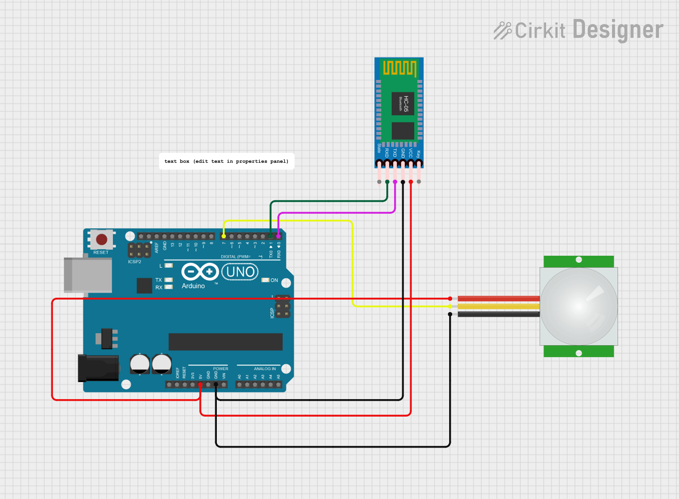
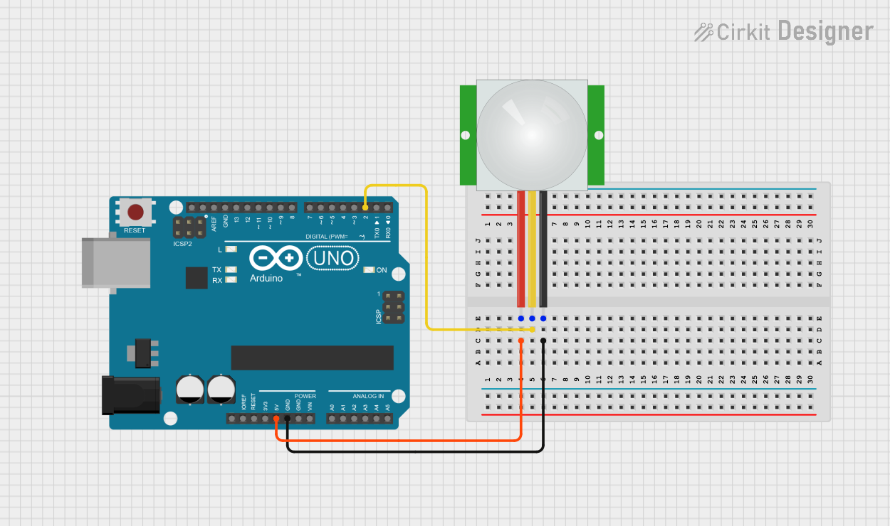
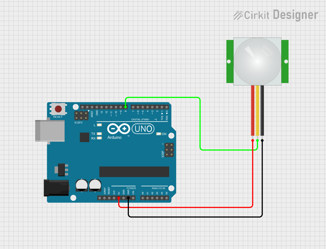
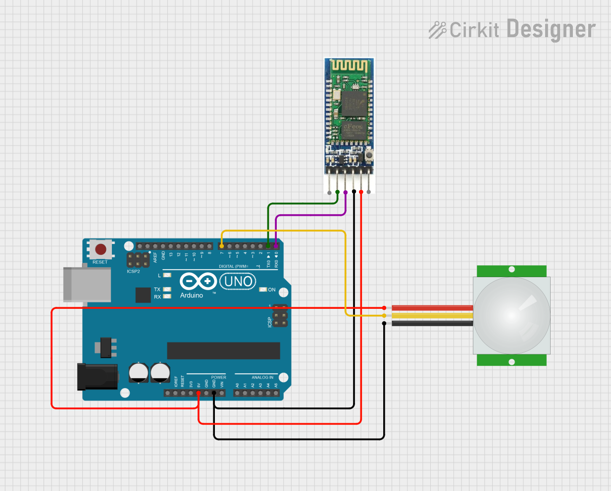
Example Circuit with Arduino UNO
Below is an example of how to connect and use a PIR sensor with an Arduino UNO to control an LED:
Circuit Connections
- PIR Sensor:
- VCC → 5V on Arduino
- GND → GND on Arduino
- OUT → Digital Pin 2 on Arduino
- LED:
- Positive leg → Digital Pin 13 on Arduino (with a 220Ω resistor in series)
- Negative leg → GND on Arduino
Arduino Code
// PIR Sensor and LED Example with Arduino UNO
// Connect PIR sensor OUT pin to Arduino Digital Pin 2
// Connect an LED to Digital Pin 13 (with a 220Ω resistor)

#define PIR_PIN 2  // Define the PIR sensor output pin
#define LED_PIN 13 // Define the LED pin

void setup() {
  pinMode(PIR_PIN, INPUT);  // Set PIR sensor pin as input
  pinMode(LED_PIN, OUTPUT); // Set LED pin as output
  Serial.begin(9600);       // Initialize serial communication
  Serial.println("PIR Sensor Test Initialized");
}

void loop() {
  int motionDetected = digitalRead(PIR_PIN); // Read PIR sensor output
  if (motionDetected == HIGH) {
    // Motion detected
    digitalWrite(LED_PIN, HIGH); // Turn on LED
    Serial.println("Motion Detected!");
  } else {
    // No motion detected
    digitalWrite(LED_PIN, LOW); // Turn off LED
  }
  delay(100); // Small delay to stabilize readings
}
Important Considerations and Best Practices
- Avoid Direct Sunlight: PIR sensors can be affected by direct sunlight or heat sources, leading to false triggers.
- Minimize Noise: Use decoupling capacitors near the power pins to reduce electrical noise.
- Placement: Install the sensor at an appropriate height and angle to maximize its detection range.
- Warm-up Time: Always allow the sensor to stabilize for ~30 seconds after powering it on.
Troubleshooting and FAQs
Common Issues and Solutions
False Triggers:
- Cause: Heat sources, sunlight, or electrical noise.
- Solution: Shield the sensor from direct heat sources and use decoupling capacitors.
No Detection:
- Cause: Incorrect wiring or insufficient power supply.
- Solution: Double-check the connections and ensure the power supply meets the sensor's requirements.
Output Stays HIGH:
- Cause: Sensitivity or time delay settings are too high.
- Solution: Adjust the potentiometers to lower the sensitivity or time delay.
Output Stays LOW:
- Cause: Sensor is not detecting motion or is malfunctioning.
- Solution: Verify the detection range and ensure the sensor is not obstructed.
FAQs
Q1: Can the PIR sensor detect motion through glass?
A1: No, PIR sensors cannot detect motion through glass as infrared radiation does not pass through it effectively.
Q2: How do I increase the detection range?
A2: Adjust the sensitivity potentiometer on the sensor module. Note that increasing sensitivity may also increase false triggers.
Q3: Can I use the PIR sensor with a 3.3V microcontroller?
A3: Yes, but ensure the sensor's output voltage is compatible with the microcontroller's input voltage levels.
Q4: Why does the sensor take time to stabilize after powering on?
A4: The sensor requires a warm-up period to calibrate its internal circuitry and avoid false triggers.
By following this documentation, you can effectively integrate a PIR sensor into your projects for reliable motion detection.