How to Use ENS161_Evaluation_Kit_SPI: Examples, Pinouts, and Specs
Introduction
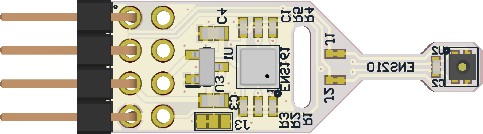
The ENS161 Evaluation Kit (ENS161_EvalKit_v3.3_SPI), manufactured by ScioSense, is a development tool designed to test and evaluate the capabilities of the ENS161 air quality sensor. The ENS161 sensor is a digital metal-oxide gas sensor capable of detecting various gases, including volatile organic compounds (VOCs) and nitrogen oxides (NOx). This evaluation kit features a Serial Peripheral Interface (SPI) for seamless communication with microcontrollers and other devices, making it ideal for prototyping and integration into air quality monitoring systems.
Explore Projects Built with ENS161_Evaluation_Kit_SPI
Explore Projects Built with ENS161_Evaluation_Kit_SPI
Common Applications and Use Cases
- Indoor air quality monitoring
- Smart home and building automation
- HVAC systems
- Air purifiers and ventilation systems
- IoT-based environmental sensing
Technical Specifications
The ENS161 Evaluation Kit is designed to simplify the evaluation of the ENS161 sensor. Below are the key technical details:
Key Technical Details
| Parameter | Value |
|---|---|
| Supply Voltage | 3.3V |
| Communication Interface | SPI |
| Operating Temperature Range | -40°C to +85°C |
| Power Consumption | < 10 mW (typical) |
| Sensor Type | Metal-oxide gas sensor |
| Measured Gases | VOCs, NOx |
| Dimensions | 25 mm x 25 mm x 5 mm |
Pin Configuration and Descriptions
The ENS161 Evaluation Kit features a standard SPI interface with the following pinout:
| Pin Name | Pin Number | Description |
|---|---|---|
| VCC | 1 | Power supply input (3.3V) |
| GND | 2 | Ground |
| SCLK | 3 | SPI clock input |
| MOSI | 4 | SPI Master Out Slave In (data input to ENS161) |
| MISO | 5 | SPI Master In Slave Out (data output from ENS161) |
| CS | 6 | Chip Select (active low) |
| INT | 7 | Interrupt output (optional, for event signaling) |
Usage Instructions
How to Use the ENS161 Evaluation Kit in a Circuit
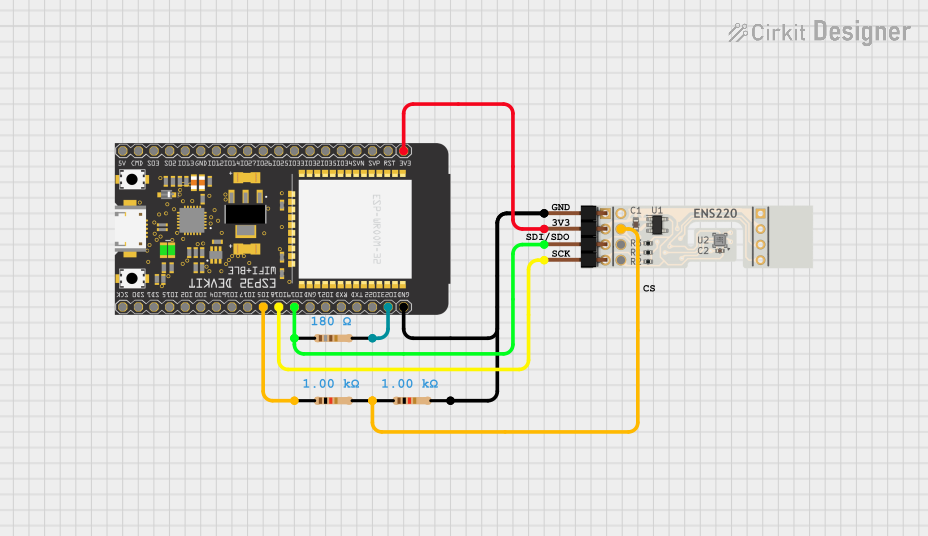
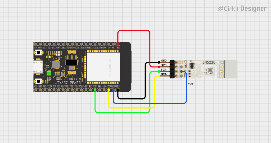
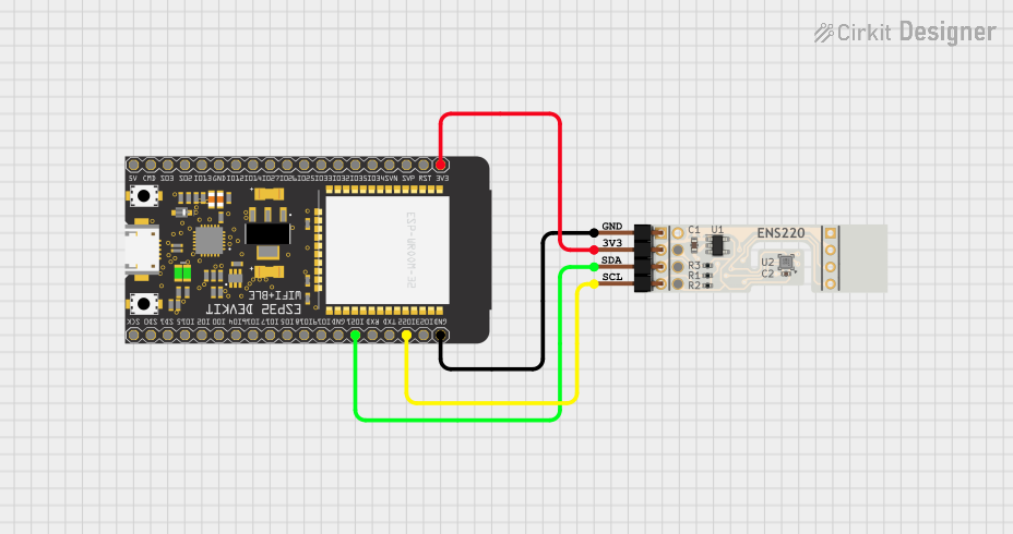
- Power Supply: Connect the VCC pin to a 3.3V power source and the GND pin to ground.
- SPI Communication: Connect the SCLK, MOSI, MISO, and CS pins to the corresponding SPI pins on your microcontroller.
- Interrupt Pin (Optional): If required, connect the INT pin to a GPIO pin on your microcontroller to handle sensor events.
- Initialization: Configure the SPI interface on your microcontroller with the following settings:
- Clock polarity (CPOL): 0
- Clock phase (CPHA): 0
- Data order: MSB first
- Data Reading: Use SPI commands to read sensor data and interpret the results according to the ENS161 datasheet.
Important Considerations and Best Practices
- Ensure the power supply is stable and within the specified range (3.3V).
- Use proper pull-up or pull-down resistors on the SPI lines if required by your microcontroller.
- Avoid placing the sensor in environments with high humidity or condensation, as this may affect its performance.
- Allow the sensor to warm up for a few minutes after power-up to ensure accurate readings.
Example Code for Arduino UNO
Below is an example of how to interface the ENS161 Evaluation Kit with an Arduino UNO using SPI:
#include <SPI.h>

// Define SPI pins for the ENS161 Evaluation Kit
const int CS_PIN = 10; // Chip Select pin

void setup() {
  // Initialize serial communication for debugging
  Serial.begin(9600);

  // Configure SPI settings
  SPI.begin();
  pinMode(CS_PIN, OUTPUT);
  digitalWrite(CS_PIN, HIGH); // Set CS pin to idle state

  Serial.println("ENS161 Evaluation Kit SPI Example");
}

void loop() {
  // Example: Read data from the ENS161 sensor
  digitalWrite(CS_PIN, LOW); // Select the ENS161 sensor
  byte command = 0x01; // Example command to read data
  byte response = SPI.transfer(command); // Send command and receive response
  digitalWrite(CS_PIN, HIGH); // Deselect the sensor

  // Print the received data
  Serial.print("Sensor Data: ");
  Serial.println(response, HEX);

  delay(1000); // Wait 1 second before the next read
}
Notes:
- Replace
0x01with the actual command to read data from the ENS161 sensor, as specified in the ENS161 datasheet. - Ensure the SPI library is properly configured for your Arduino board.
Troubleshooting and FAQs
Common Issues and Solutions
No Data from the Sensor
- Cause: Incorrect SPI configuration or wiring.
- Solution: Verify the SPI settings (CPOL, CPHA, data order) and ensure all connections are secure.
Inconsistent Readings
- Cause: Insufficient warm-up time or unstable power supply.
- Solution: Allow the sensor to warm up for at least 5 minutes and ensure a stable 3.3V power source.
Sensor Not Responding
- Cause: Chip Select (CS) pin not properly controlled.
- Solution: Ensure the CS pin is set to LOW before sending SPI commands and HIGH after communication.
FAQs
Q: Can the ENS161 Evaluation Kit be used with I2C instead of SPI?
A: No, this version of the evaluation kit (ENS161_EvalKit_v3.3_SPI) is specifically designed for SPI communication. For I2C, a different version of the kit may be required.
Q: How do I interpret the sensor data?
A: Refer to the ENS161 datasheet for details on the data format and how to convert raw sensor readings into meaningful air quality metrics.
Q: Is the ENS161 sensor suitable for outdoor use?
A: The ENS161 is primarily designed for indoor air quality monitoring. Outdoor use may require additional protection against environmental factors like humidity and temperature extremes.