How to Use 8:1 Analog Multiplexer: Examples, Pinouts, and Specs
Documentation for CD4051 8:1 Analog Multiplexer
Manufacturer: Texas Instruments
Part ID: CD4051
1. Introduction
The CD4051 is an 8:1 analog multiplexer/demultiplexer manufactured by Texas Instruments. It is a versatile integrated circuit (IC) that allows the selection of one of eight analog input signals and forwards the selected input to a single output line. The selection is controlled by three digital select lines. This IC is widely used in applications requiring signal routing, data acquisition, and analog signal processing.
Common Applications
- Signal multiplexing in data acquisition systems
- Audio signal routing
- Sensor signal selection
- Analog-to-digital conversion (ADC) channel selection
- Test equipment and instrumentation
2. Technical Specifications
The following table outlines the key technical specifications of the CD4051:
| Parameter | Value |
|---|---|
| Supply Voltage (V_DD) | 3V to 18V |
| Input Voltage Range | 0V to V_DD |
| On-Resistance (R_ON) | 125Ω (typical at V_DD = 10V) |
| Maximum Input Current | ±10mA |
| Power Dissipation | 700mW (maximum) |
| Operating Temperature Range | -55°C to +125°C |
| Control Logic Voltage Levels | Compatible with CMOS and TTL |
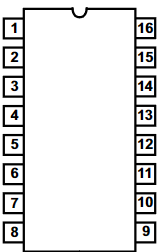
Pin Configuration and Descriptions
The CD4051 is available in a 16-pin DIP, SOIC, or TSSOP package. The pinout is as follows:
| Pin Number | Pin Name | Description |
|---|---|---|
| 1 | X0 | Analog Input 0 |
| 2 | X1 | Analog Input 1 |
| 3 | X2 | Analog Input 2 |
| 4 | X3 | Analog Input 3 |
| 5 | X4 | Analog Input 4 |
| 6 | X5 | Analog Input 5 |
| 7 | X6 | Analog Input 6 |
| 8 | V_EE | Negative Supply Voltage (typically 0V for single-supply operation) |
| 9 | X7 | Analog Input 7 |
| 10 | COM | Common Output (or Input in demultiplexer mode) |
| 11 | INH | Inhibit Control (active HIGH, disables all channels when HIGH) |
| 12 | A | Select Line A (LSB) |
| 13 | B | Select Line B |
| 14 | C | Select Line C (MSB) |
| 15 | V_DD | Positive Supply Voltage |
| 16 | V_SS | Ground (0V reference) |
3. Usage Instructions
Connecting the CD4051 in a Circuit
Power Supply:
- Connect the V_DD pin to the positive supply voltage (e.g., 5V or 12V).
- Connect the V_SS pin to ground (0V).
- For single-supply operation, connect V_EE to ground. For dual-supply operation, connect V_EE to a negative voltage (e.g., -5V).
Input and Output Connections:
- Connect up to eight analog signals to the X0 to X7 pins.
- The selected signal will appear on the COM pin.
Control Logic:
Use the A, B, and C pins to select the desired input channel. These pins accept digital logic levels (0 or 1).
The binary combination of A, B, and C determines the active input channel:
C B A Selected Input 0 0 0 X0 0 0 1 X1 0 1 0 X2 0 1 1 X3 1 0 0 X4 1 0 1 X5 1 1 0 X6 1 1 1 X7
Inhibit Control:
- When the INH pin is HIGH, all channels are disabled, and the COM pin is disconnected.
Best Practices
- Use decoupling capacitors (e.g., 0.1µF) between V_DD and V_SS to reduce noise.
- Avoid exceeding the maximum voltage ratings to prevent damage to the IC.
- For high-impedance signals, consider buffering the output to minimize loading effects.
4. Example: Using CD4051 with Arduino UNO
The following example demonstrates how to use the CD4051 to read multiple analog signals with an Arduino UNO.
Circuit Diagram
- Connect the X0 to X7 pins to eight analog signal sources (e.g., potentiometers).
- Connect the COM pin to the Arduino's A0 pin.
- Connect the A, B, and C pins to Arduino digital pins 2, 3, and 4, respectively.
- Connect V_DD to 5V, V_SS to GND, and V_EE to GND.
Arduino Code
// Define control pins for the CD4051
const int selectPinA = 2; // Select line A
const int selectPinB = 3; // Select line B
const int selectPinC = 4; // Select line C
const int analogInput = A0; // Common output connected to Arduino A0

void setup() {
  // Set select pins as outputs
  pinMode(selectPinA, OUTPUT);
  pinMode(selectPinB, OUTPUT);
  pinMode(selectPinC, OUTPUT);

  // Initialize serial communication for debugging
  Serial.begin(9600);
}

void loop() {
  for (int channel = 0; channel < 8; channel++) {
    // Set the select pins to the binary representation of the channel
    digitalWrite(selectPinA, channel & 0x01); // LSB
    digitalWrite(selectPinB, (channel >> 1) & 0x01);
    digitalWrite(selectPinC, (channel >> 2) & 0x01); // MSB

    // Read the analog value from the selected channel
    int analogValue = analogRead(analogInput);

    // Print the channel number and its value
    Serial.print("Channel ");
    Serial.print(channel);
    Serial.print(": ");
    Serial.println(analogValue);

    delay(500); // Wait for 500ms before reading the next channel
  }
}
5. Troubleshooting and FAQs
Common Issues
No Output Signal on COM Pin:
- Ensure the INH pin is LOW.
- Verify that the control logic pins (A, B, C) are correctly set.
Incorrect Channel Selection:
- Check the binary values applied to the select pins.
- Ensure proper connections between the Arduino and the CD4051.
Signal Distortion or Noise:
- Use decoupling capacitors to stabilize the power supply.
- Avoid long wires for analog signals to minimize interference.
FAQs
Q1: Can the CD4051 handle digital signals?
A1: Yes, the CD4051 can multiplex both analog and digital signals, provided the voltage levels are within the specified range.
Q2: Can I use the CD4051 for bidirectional signal routing?
A2: Yes, the CD4051 supports bidirectional operation, allowing signals to flow in either direction.
Q3: What is the maximum switching speed of the CD4051?
A3: The switching speed depends on the supply voltage and load capacitance. Refer to the datasheet for detailed timing characteristics.
This documentation provides a comprehensive guide to using the CD4051 8:1 analog multiplexer. For further details, refer to the official Texas Instruments datasheet.
Explore Projects Built with 8:1 Analog Multiplexer


Explore Projects Built with 8:1 Analog Multiplexer