How to Use L298D: Examples, Pinouts, and Specs
Introduction
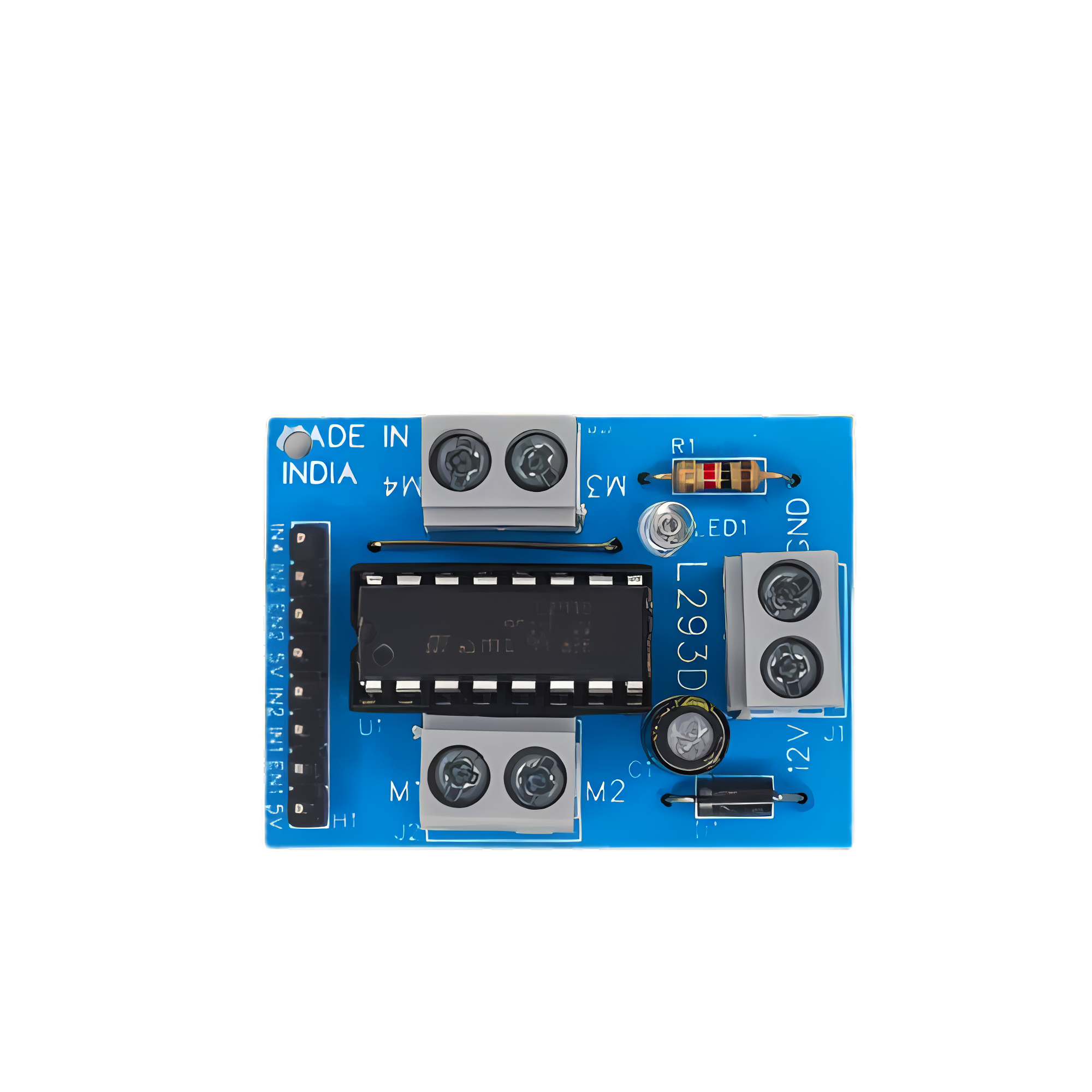
The L298D is a versatile dual H-Bridge motor driver IC designed to control the speed and direction of two DC motors or one stepper motor. It is widely used in robotics, automation, and various motor control applications due to its ability to handle up to 2A of current per channel and operate at voltages ranging from 5V to 46V. This documentation provides a comprehensive guide to understanding, using, and troubleshooting the L298D.
Explore Projects Built with L298D
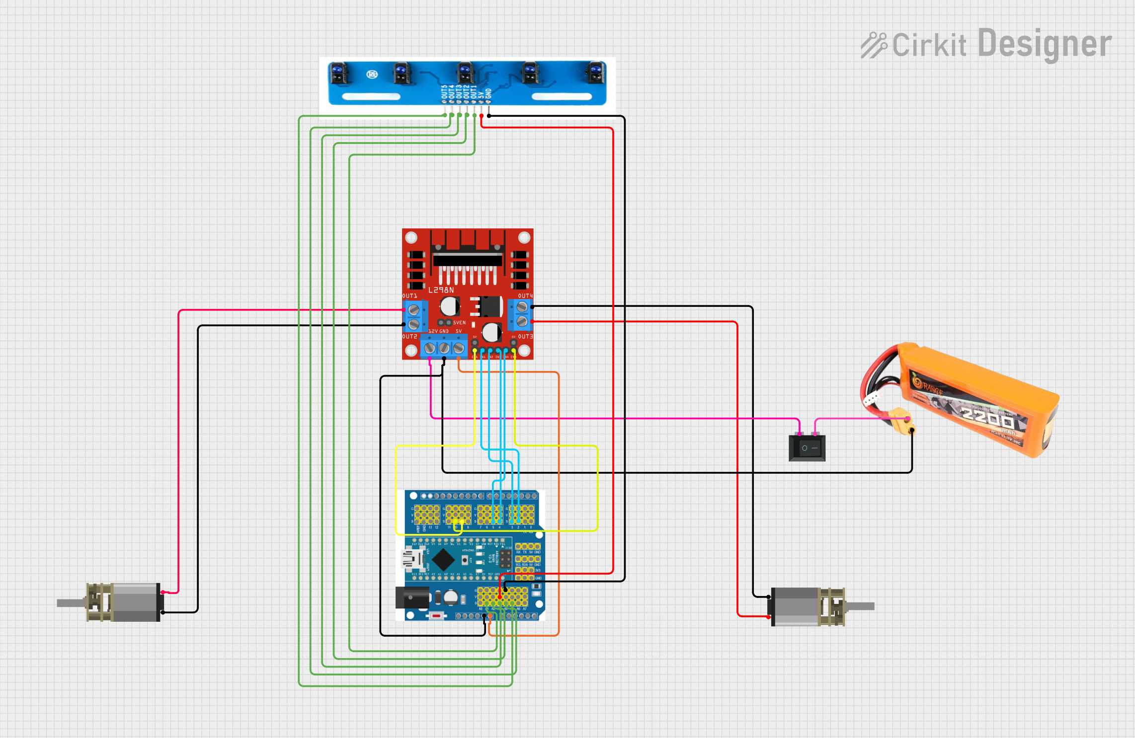

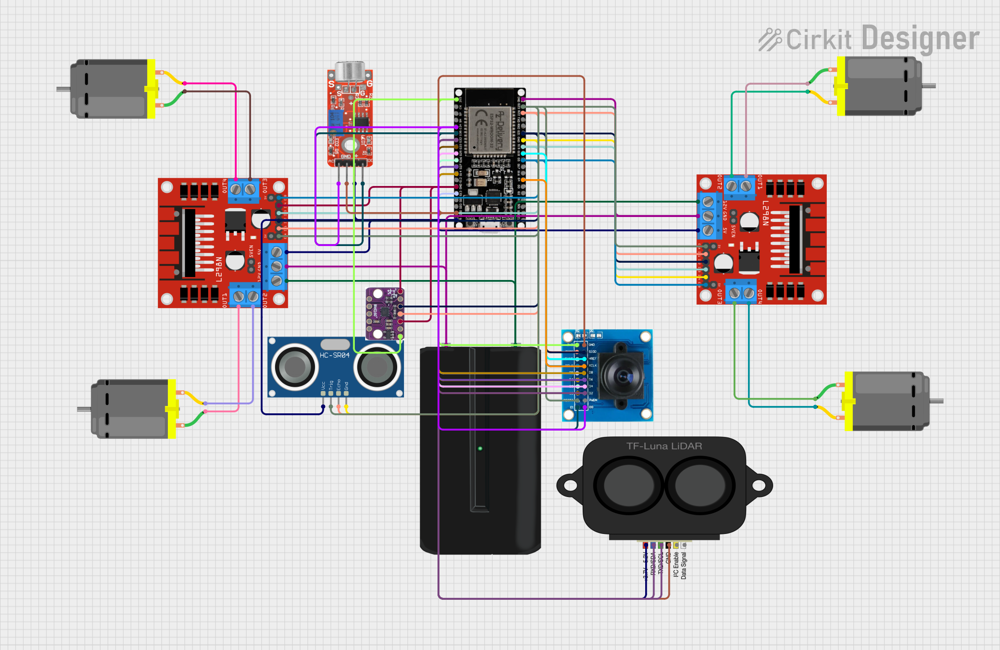
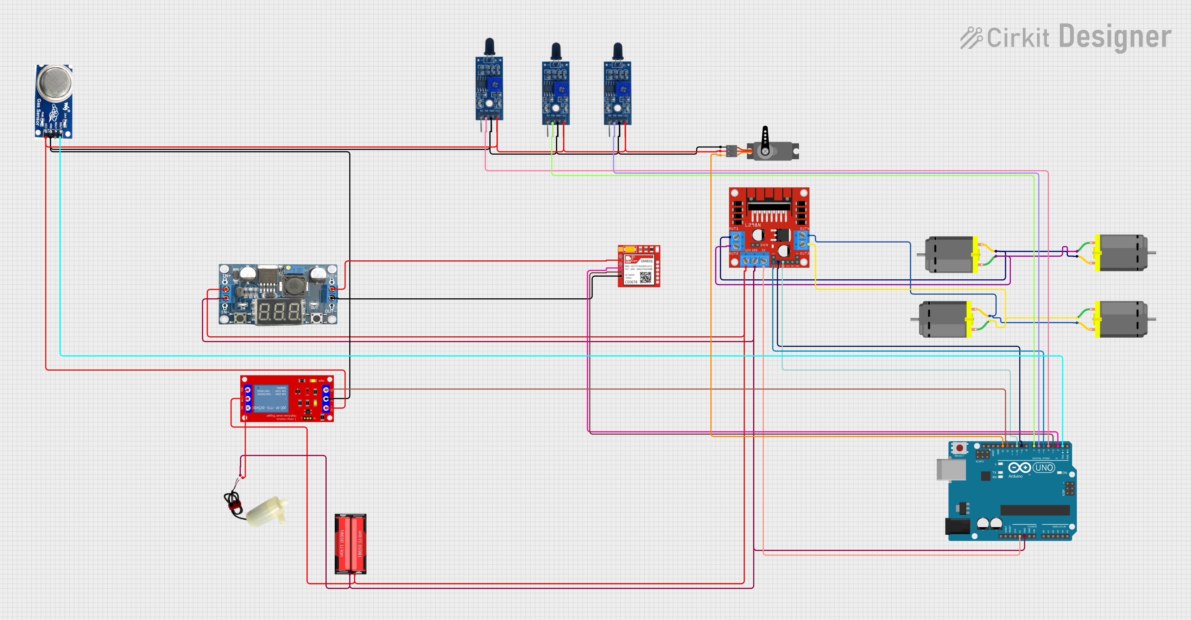
Explore Projects Built with L298D
Technical Specifications
Key Technical Details
| Parameter | Value |
|---|---|
| Supply Voltage | 5V to 46V |
| Output Current | 2A per channel (max) |
| Peak Output Current | 3A per channel (non-repetitive) |
| Logic Voltage | 5V |
| Control Logic | TTL compatible |
| Power Dissipation | 25W (at Tcase = 75°C) |
| Operating Temperature | -25°C to +130°C |
Pin Configuration and Descriptions
| Pin No. | Pin Name | Description |
|---|---|---|
| 1 | Enable A | Enables the H-Bridge A (active high) |
| 2 | Input 1 | Logic input 1 for H-Bridge A |
| 3 | Output 1 | Output 1 for H-Bridge A |
| 4 | GND | Ground |
| 5 | GND | Ground |
| 6 | Output 2 | Output 2 for H-Bridge A |
| 7 | Input 2 | Logic input 2 for H-Bridge A |
| 8 | Vss | Supply voltage for the logic circuitry (5V) |
| 9 | Enable B | Enables the H-Bridge B (active high) |
| 10 | Input 3 | Logic input 3 for H-Bridge B |
| 11 | Output 3 | Output 3 for H-Bridge B |
| 12 | GND | Ground |
| 13 | GND | Ground |
| 14 | Output 4 | Output 4 for H-Bridge B |
| 15 | Input 4 | Logic input 4 for H-Bridge B |
| 16 | Vs | Supply voltage for the motor (5V to 46V) |
Usage Instructions
How to Use the L298D in a Circuit
Power Connections:
- Connect the
Vspin (Pin 16) to the motor power supply (5V to 46V). - Connect the
Vsspin (Pin 8) to the logic power supply (5V). - Connect the
GNDpins (Pins 4, 5, 12, 13) to the ground of the power supply.
- Connect the
Motor Connections:
- Connect the motor terminals to the output pins (
Output 1andOutput 2for Motor A,Output 3andOutput 4for Motor B).
- Connect the motor terminals to the output pins (
Control Connections:
- Connect the control logic inputs (
Input 1,Input 2,Input 3,Input 4) to the microcontroller or control circuit. - Enable the H-Bridge channels by setting
Enable AandEnable Bhigh.
- Connect the control logic inputs (
Important Considerations and Best Practices
- Heat Dissipation: The L298D can dissipate a significant amount of heat. Ensure proper heat sinking or cooling to prevent overheating.
- Current Limiting: Use current limiting resistors or a current sensing circuit to protect the IC from overcurrent conditions.
- Decoupling Capacitors: Place decoupling capacitors close to the power supply pins to filter out noise and stabilize the voltage.
Example Code for Arduino UNO
// Example code to control two DC motors using L298D and Arduino UNO

// Define control pins for Motor A
const int enA = 9;
const int in1 = 8;
const int in2 = 7;

// Define control pins for Motor B
const int enB = 10;
const int in3 = 6;
const int in4 = 5;

void setup() {
  // Set all the motor control pins to outputs
  pinMode(enA, OUTPUT);
  pinMode(in1, OUTPUT);
  pinMode(in2, OUTPUT);
  pinMode(enB, OUTPUT);
  pinMode(in3, OUTPUT);
  pinMode(in4, OUTPUT);

  // Initialize motors to off
  digitalWrite(enA, LOW);
  digitalWrite(enB, LOW);
}

void loop() {
  // Example: Move Motor A forward
  digitalWrite(in1, HIGH);
  digitalWrite(in2, LOW);
  analogWrite(enA, 255); // Set speed to maximum

  // Example: Move Motor B backward
  digitalWrite(in3, LOW);
  digitalWrite(in4, HIGH);
  analogWrite(enB, 255); // Set speed to maximum

  delay(2000); // Run motors for 2 seconds

  // Stop motors
  analogWrite(enA, 0);
  analogWrite(enB, 0);

  delay(2000); // Wait for 2 seconds
}
Troubleshooting and FAQs
Common Issues and Solutions
Motor Not Running:
- Check Power Supply: Ensure the motor power supply is connected and providing the correct voltage.
- Verify Connections: Double-check all connections, especially the control and power pins.
- Enable Pins: Ensure the
Enable AandEnable Bpins are set high.
Overheating:
- Heat Sink: Attach a heat sink to the L298D to dissipate heat.
- Current Limiting: Ensure the current does not exceed the maximum rating of 2A per channel.
Erratic Motor Behavior:
- Decoupling Capacitors: Add decoupling capacitors close to the power supply pins.
- Noise Filtering: Use proper filtering techniques to reduce electrical noise.
FAQs
Q1: Can the L298D control stepper motors? A1: Yes, the L298D can control stepper motors by driving the coils in a specific sequence.
Q2: What is the maximum voltage the L298D can handle? A2: The L298D can handle a maximum motor supply voltage of 46V.
Q3: How do I control the speed of the motors?
A3: The speed of the motors can be controlled using PWM signals on the Enable A and Enable B pins.
Q4: Can I use the L298D with a 3.3V microcontroller? A4: The L298D is designed for 5V logic levels. You may need level shifters to interface with a 3.3V microcontroller.
By following this documentation, users can effectively utilize the L298D dual H-Bridge motor driver IC in their projects, ensuring reliable and efficient motor control.