Cirkit Designer Logo
Cirkit Designer
Your all-in-one circuit design IDE
Home / 
Component Documentation

How to Use 1.2/1.3 GHz antenna: Examples, Pinouts, and Specs

Image of 1.2/1.3 GHz antenna
Cirkit Designer LogoDesign with 1.2/1.3 GHz antenna in Cirkit Designer

Introduction

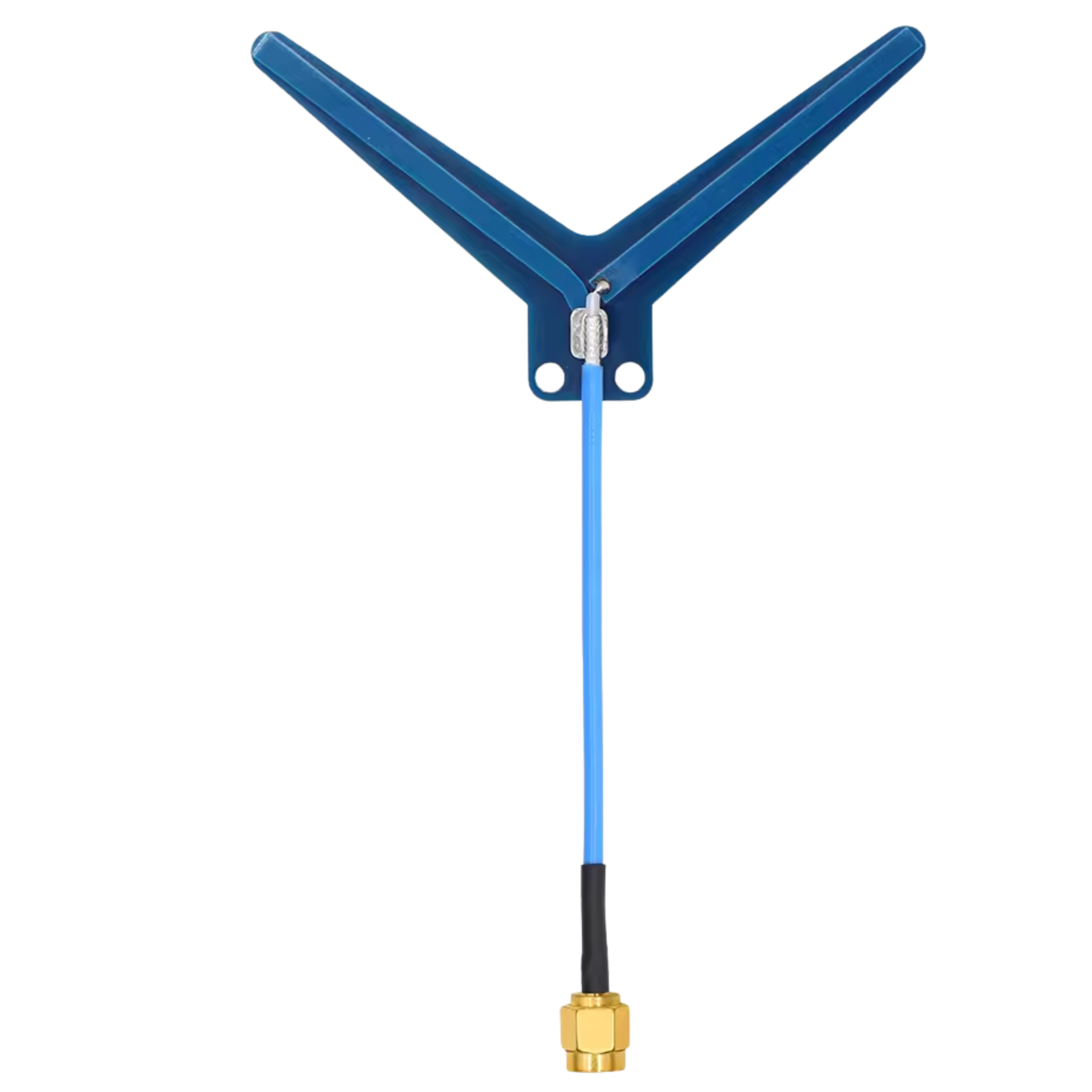
The 1.2/1.3 GHz antenna is a specialized component designed to operate within the frequency range of 1.2 to 1.3 GHz. It is widely used in wireless communication applications, including RFID systems, remote sensing, telemetry, and amateur radio. This antenna is optimized for high-frequency signal transmission and reception, ensuring reliable performance in various environments.

Common applications and use cases:

  • RFID systems: Used for tracking and identification in industrial and commercial settings.
  • Remote sensing: Supports data collection in environmental monitoring and scientific research.
  • Telemetry: Enables wireless data transmission in aerospace, automotive, and medical fields.
  • Amateur radio: Popular among hobbyists for long-range communication.

Explore Projects Built with 1.2/1.3 GHz antenna

Use Cirkit Designer to design, explore, and prototype these projects online. Some projects support real-time simulation. Click "Open Project" to start designing instantly!
Satellite Compass and Network-Integrated GPS Data Processing System
Image of GPS 시스템 측정 구성도_241016: A project utilizing 1.2/1.3 GHz antenna in a practical application
This circuit comprises a satellite compass, a mini PC, two GPS antennas, power supplies, a network switch, media converters, and an atomic rubidium clock. The satellite compass is powered by a triple output DC power supply and interfaces with an RS232 splitter for 1PPS signals. The mini PCs are connected to the USRP B200 devices via USB for data and power, and to media converters via Ethernet, which in turn connect to a network switch using fiber optic links. The antennas are connected to the USRP B200s through RF directional couplers, and the atomic clock provides a 1PPS input to the RS232 splitter.
Cirkit Designer LogoOpen Project in Cirkit Designer
Satellite-Based Timing and Navigation System with SDR and Atomic Clock Synchronization
Image of GPS 시스템 측정 구성도_Confirm: A project utilizing 1.2/1.3 GHz antenna in a practical application
This circuit appears to be a complex system involving power supply management, GPS and timing synchronization, and data communication. It includes a SI-TEX G1 Satellite Compass for GPS data, an XHTF1021 Atomic Rubidium Clock for precise timing, and Ettus USRP B200 units for software-defined radio communication. Power is supplied through various SMPS units and distributed via terminal blocks and DC jacks. Data communication is facilitated by Beelink MINI S12 N95 computers, RS232 splitters, and a 1000BASE-T Media Converter for network connectivity. RF Directional Couplers are used to interface antennas with the USRP units, and the entire system is likely contained within cases for protection and organization.
Cirkit Designer LogoOpen Project in Cirkit Designer
Laptop-Connected Adalm Pluto SDR with Dual Antennas
Image of Zidan Project: A project utilizing 1.2/1.3 GHz antenna in a practical application
This circuit connects an Adalm Pluto Software Defined Radio (SDR) to a laptop via a Type-B to USB cable, allowing the laptop to control the SDR and process signals. Additionally, two antennas are connected to the Adalm Pluto SDR, which are likely used for transmitting and receiving radio signals as part of the SDR's functionality.
Cirkit Designer LogoOpen Project in Cirkit Designer
ESP32-Controlled FM Radio Transmitter
Image of bluetooth: A project utilizing 1.2/1.3 GHz antenna in a practical application
This circuit features an ESP32 microcontroller connected to a DSP PLL Stereo FM Transmitter, with the ESP32's digital pin D26 interfacing with the transmitter's auxiliary input. The ESP32 and the FM transmitter are configured for serial communication via the ESP32's TX0 to the transmitter's RX and RX0 to the transmitter's TX. The circuit is powered by a 5V battery, with the ESP32's Vin and GND connected to the battery's positive and negative terminals, respectively, and the FM transmitter's Vcc and Ground also connected to the ESP32's 3V3 and GND. An antenna is connected to the FM transmitter for signal broadcasting.
Cirkit Designer LogoOpen Project in Cirkit Designer

Explore Projects Built with 1.2/1.3 GHz antenna

Use Cirkit Designer to design, explore, and prototype these projects online. Some projects support real-time simulation. Click "Open Project" to start designing instantly!
Image of GPS 시스템 측정 구성도_241016: A project utilizing 1.2/1.3 GHz antenna in a practical application
Satellite Compass and Network-Integrated GPS Data Processing System
This circuit comprises a satellite compass, a mini PC, two GPS antennas, power supplies, a network switch, media converters, and an atomic rubidium clock. The satellite compass is powered by a triple output DC power supply and interfaces with an RS232 splitter for 1PPS signals. The mini PCs are connected to the USRP B200 devices via USB for data and power, and to media converters via Ethernet, which in turn connect to a network switch using fiber optic links. The antennas are connected to the USRP B200s through RF directional couplers, and the atomic clock provides a 1PPS input to the RS232 splitter.
Cirkit Designer LogoOpen Project in Cirkit Designer
Image of GPS 시스템 측정 구성도_Confirm: A project utilizing 1.2/1.3 GHz antenna in a practical application
Satellite-Based Timing and Navigation System with SDR and Atomic Clock Synchronization
This circuit appears to be a complex system involving power supply management, GPS and timing synchronization, and data communication. It includes a SI-TEX G1 Satellite Compass for GPS data, an XHTF1021 Atomic Rubidium Clock for precise timing, and Ettus USRP B200 units for software-defined radio communication. Power is supplied through various SMPS units and distributed via terminal blocks and DC jacks. Data communication is facilitated by Beelink MINI S12 N95 computers, RS232 splitters, and a 1000BASE-T Media Converter for network connectivity. RF Directional Couplers are used to interface antennas with the USRP units, and the entire system is likely contained within cases for protection and organization.
Cirkit Designer LogoOpen Project in Cirkit Designer
Image of Zidan Project: A project utilizing 1.2/1.3 GHz antenna in a practical application
Laptop-Connected Adalm Pluto SDR with Dual Antennas
This circuit connects an Adalm Pluto Software Defined Radio (SDR) to a laptop via a Type-B to USB cable, allowing the laptop to control the SDR and process signals. Additionally, two antennas are connected to the Adalm Pluto SDR, which are likely used for transmitting and receiving radio signals as part of the SDR's functionality.
Cirkit Designer LogoOpen Project in Cirkit Designer
Image of bluetooth: A project utilizing 1.2/1.3 GHz antenna in a practical application
ESP32-Controlled FM Radio Transmitter
This circuit features an ESP32 microcontroller connected to a DSP PLL Stereo FM Transmitter, with the ESP32's digital pin D26 interfacing with the transmitter's auxiliary input. The ESP32 and the FM transmitter are configured for serial communication via the ESP32's TX0 to the transmitter's RX and RX0 to the transmitter's TX. The circuit is powered by a 5V battery, with the ESP32's Vin and GND connected to the battery's positive and negative terminals, respectively, and the FM transmitter's Vcc and Ground also connected to the ESP32's 3V3 and GND. An antenna is connected to the FM transmitter for signal broadcasting.
Cirkit Designer LogoOpen Project in Cirkit Designer

Technical Specifications

The following table outlines the key technical specifications of the 1.2/1.3 GHz antenna:

Parameter Specification
Frequency Range 1.2 GHz to 1.3 GHz
Gain 6 dBi to 12 dBi (varies by model)
Polarization Linear or Circular
Impedance 50 Ω
VSWR (Voltage Standing Wave Ratio) ≤ 1.5:1
Connector Type SMA, N-Type, or custom
Power Handling Capacity Up to 50 W
Operating Temperature -40°C to +85°C
Dimensions Varies (e.g., 20 cm to 50 cm length)
Weight Typically 200 g to 500 g

Pin Configuration and Descriptions

The 1.2/1.3 GHz antenna typically has a single RF connector for interfacing with the circuit or device. Below is a description of the connector pin:

Pin/Connector Description
RF Connector Connects the antenna to the transmitter or receiver. Common types include SMA and N-Type.

Usage Instructions

How to Use the Antenna in a Circuit

  1. Select a compatible RF connector: Ensure the antenna's connector type (e.g., SMA or N-Type) matches the connector on your device or circuit.
  2. Mount the antenna: Position the antenna in a location with minimal obstructions to maximize signal strength. For outdoor use, ensure the antenna is weatherproofed.
  3. Connect to the RF circuit: Attach the antenna to the transmitter or receiver using a low-loss coaxial cable. Maintain a secure connection to minimize signal loss.
  4. Tune the system: Verify that the operating frequency of your transmitter or receiver is within the 1.2 to 1.3 GHz range. Adjust the system settings as needed to optimize performance.

Important Considerations and Best Practices

  • Impedance matching: Ensure the antenna impedance (50 Ω) matches the impedance of your RF circuit to prevent signal reflection and power loss.
  • Minimize VSWR: Use high-quality cables and connectors to maintain a low VSWR (≤ 1.5:1) for efficient signal transmission.
  • Avoid interference: Place the antenna away from sources of electromagnetic interference (EMI), such as power lines or other RF devices.
  • Secure mounting: Use appropriate mounting hardware to prevent the antenna from shifting or falling during operation.
  • Weatherproofing: For outdoor installations, use weatherproof enclosures or coatings to protect the antenna from environmental damage.

Example: Connecting to an Arduino UNO

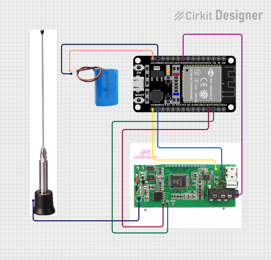
While the 1.2/1.3 GHz antenna is not directly connected to an Arduino UNO, it can be used with RF modules (e.g., LoRa or telemetry modules) that interface with the Arduino. Below is an example of using an RF module with the antenna and Arduino:

#include <SPI.h>
#include <LoRa.h>

// Define LoRa module pins
#define SCK 5    // Clock pin
#define MISO 19  // Master In Slave Out
#define MOSI 27  // Master Out Slave In
#define SS 18    // Slave Select
#define RST 14   // Reset pin
#define DIO0 26  // Interrupt pin

void setup() {
  Serial.begin(9600); // Initialize serial communication
  while (!Serial);

  Serial.println("Initializing LoRa module...");

  // Initialize LoRa module
  if (!LoRa.begin(1250E6)) { // Set frequency to 1.25 GHz (within 1.2-1.3 GHz range)
    Serial.println("LoRa initialization failed!");
    while (1);
  }

  Serial.println("LoRa initialized successfully!");
}

void loop() {
  // Send a test message
  Serial.println("Sending message...");
  LoRa.beginPacket();
  LoRa.print("Hello, 1.2/1.3 GHz antenna!");
  LoRa.endPacket();

  delay(5000); // Wait 5 seconds before sending the next message
}

Note: Ensure the RF module supports the 1.2/1.3 GHz frequency range and is connected to the antenna via a compatible RF connector.

Troubleshooting and FAQs

Common Issues and Solutions

  1. Weak signal strength:

    • Cause: Obstructions or poor antenna placement.
    • Solution: Reposition the antenna to a higher or more open location. Ensure there are no large metal objects nearby.
  2. High VSWR:

    • Cause: Impedance mismatch or damaged cable/connector.
    • Solution: Verify impedance matching and inspect cables and connectors for damage. Replace if necessary.
  3. No signal reception:

    • Cause: Incorrect frequency or faulty connections.
    • Solution: Confirm the operating frequency is within the 1.2 to 1.3 GHz range. Check all connections for proper attachment.
  4. Intermittent signal loss:

    • Cause: Environmental interference or loose connections.
    • Solution: Identify and eliminate sources of interference. Secure all connections.

FAQs

  • Q: Can this antenna be used for GPS applications?
    A: No, GPS typically operates at 1.575 GHz, which is outside the 1.2/1.3 GHz range.

  • Q: Is this antenna suitable for outdoor use?
    A: Yes, but ensure it is weatherproofed or installed in a protective enclosure.

  • Q: What is the maximum range of this antenna?
    A: The range depends on factors such as antenna gain, transmitter power, and environmental conditions. Typically, it can achieve several kilometers in open areas.

  • Q: Can I use this antenna with a Wi-Fi router?
    A: No, Wi-Fi operates at 2.4 GHz or 5 GHz, which is outside the antenna's frequency range.