How to Use m5Stack ATOM Lite: Examples, Pinouts, and Specs

 Design with m5Stack ATOM Lite in Cirkit Designer
Introduction
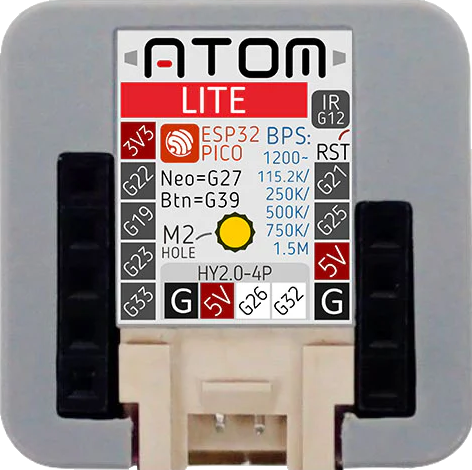
The m5Stack ATOM Lite is an ultra-compact development board designed for Internet of Things (IoT) projects and prototyping. Based on the ESP32-PICO-D4 microcontroller, it offers a rich set of features including Wi-Fi connectivity, a programmable button, and an RGB LED. This board is ideal for applications such as smart home devices, wearable electronics, and various wireless sensor networks.
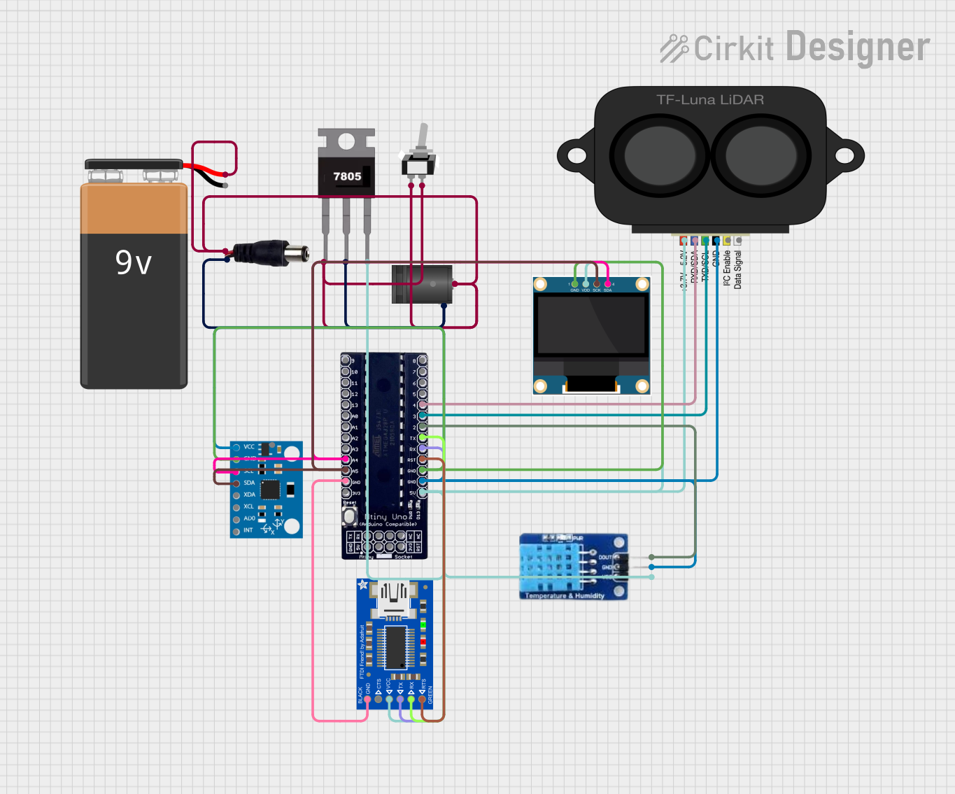
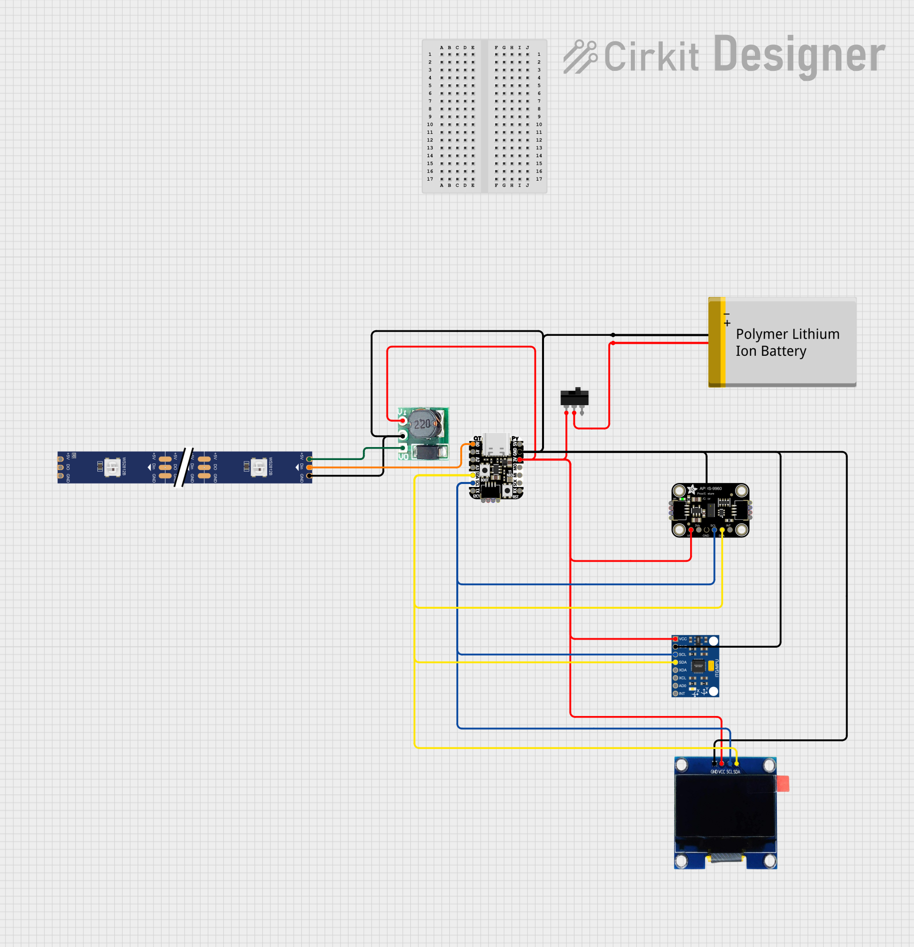
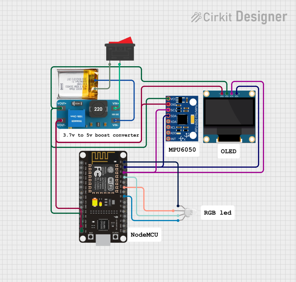
Explore Projects Built with m5Stack ATOM Lite

 Open Project in Cirkit Designer
 Open Project in Cirkit Designer
 Open Project in Cirkit Designer
 Open Project in Cirkit Designer
Explore Projects Built with m5Stack ATOM Lite

 Open Project in Cirkit Designer
 Open Project in Cirkit Designer
 Open Project in Cirkit Designer
 Open Project in Cirkit Designer
Common Applications and Use Cases
- IoT devices
- Wearable technology
- Smart home applications
- Wireless sensor networks
- Educational projects and prototyping
Technical Specifications
Key Technical Details
- Microcontroller: ESP32-PICO-D4
- Operating Voltage: 3.3V
- Input Voltage (recommended): 5V via USB-C or GPIO
- Digital I/O Pins: 5
- Analog Input Pins: 1 (ADC)
- Flash Memory: 4MB
- SRAM: 520 KB
- LED: Built-in WS2812 RGB LED
- Button: Built-in tactile switch
- Connectivity: Wi-Fi 802.11 b/g/n
- Dimensions: 24 x 24 x 10 mm
Pin Configuration and Descriptions
| Pin | Function | Description |
|---|---|---|
| G21 | GPIO | General-purpose input/output |
| G22 | GPIO | General-purpose input/output |
| G19 | GPIO | General-purpose input/output |
| G23 | GPIO | General-purpose input/output |
| G33 | ADC/GPIO | Analog-to-digital converter/general input/output |
| 5V | Power Supply | 5V input |
| GND | Ground | Ground connection |
| TX | Serial Output | Transmit pin for UART communication |
| RX | Serial Input | Receive pin for UART communication |
Usage Instructions
How to Use the Component in a Circuit
Powering the Device:
- Connect the 5V pin to a 5V power supply and GND to ground.
- Alternatively, power the ATOM Lite via the USB-C port.
Programming the Device:
- Use the USB-C connection to program the ATOM Lite from your computer.
- The board is compatible with the Arduino IDE, PlatformIO, and the ESP-IDF framework.
Connecting to Wi-Fi:
- Utilize the ESP32's Wi-Fi capabilities to connect to a network for IoT applications.
Interfacing with Sensors and Actuators:
- Use the GPIO pins to connect sensors and actuators.
- The ADC pin can be used to read analog values.
Important Considerations and Best Practices
- Ensure that the input voltage does not exceed the recommended 5V to prevent damage.
- When using Wi-Fi, consider power consumption and heat dissipation.
- Use proper ESD precautions when handling the ATOM Lite to avoid damaging the sensitive electronics.
Example Code for Arduino UNO
#include <WiFi.h>

// Replace with your network credentials
const char* ssid = "your_SSID";
const char* password = "your_PASSWORD";

void setup() {
  Serial.begin(115200);

  // Connect to Wi-Fi
  WiFi.begin(ssid, password);
  while (WiFi.status() != WL_CONNECTED) {
    delay(500);
    Serial.println("Connecting to WiFi...");
  }
  Serial.println("Connected to WiFi");
}

void loop() {
  // Implement your logic here
}
Troubleshooting and FAQs
Common Issues
- Device not powering on: Ensure the power supply is connected correctly and providing 5V.
- Cannot connect to Wi-Fi: Verify the SSID and password are correct and that the Wi-Fi network is within range.
- Programming errors: Check the USB-C cable and ensure the correct board settings in the Arduino IDE.
Solutions and Tips for Troubleshooting
- Power Issues: Use a stable 5V power source. If using USB, ensure the cable and source can provide sufficient current.
- Wi-Fi Connectivity: Reset the board and attempt to reconnect. Ensure no interference or obstacles that could affect signal strength.
- Programming: Double-check the driver installation for the USB-C port and ensure the ATOM Lite is selected as the board in your IDE.
FAQs
Q: Can I use the ATOM Lite with battery power? A: Yes, you can power the ATOM Lite with a 3.7V lithium battery connected to the 5V pin.
Q: Is the ATOM Lite compatible with MicroPython? A: Yes, the ATOM Lite supports programming with MicroPython.
Q: How do I update the firmware on the ATOM Lite? A: Firmware updates can be done through the Arduino IDE or using the esptool.py utility for advanced users.
Q: What is the range of the Wi-Fi connectivity? A: The range depends on environmental factors but typically is around 50-100 meters in open space.
For further assistance, consult the m5Stack community forums or the official m5Stack documentation.