How to Use SIM7600CE-T: Examples, Pinouts, and Specs
Introduction
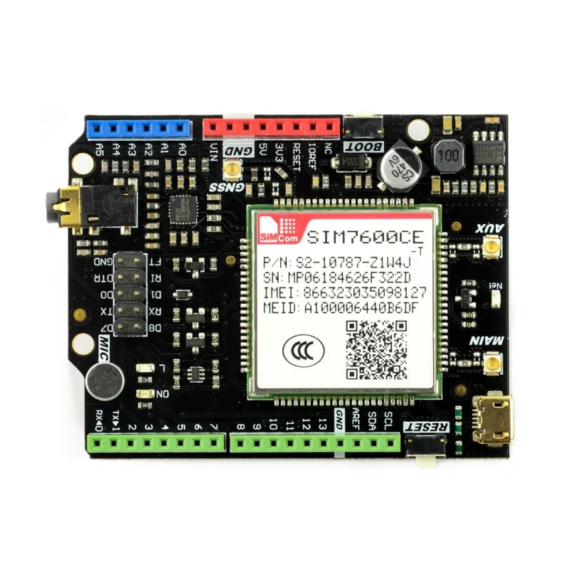
The SIM7600CE-T is a 4G LTE module manufactured by RFrobots, designed to support a wide range of communication protocols, including GSM, GPRS, and HSPA+. This versatile module is ideal for Internet of Things (IoT) applications, offering high-speed data transmission and integrated GPS functionality. Its compact design and robust features make it suitable for applications such as remote monitoring, industrial automation, vehicle tracking, and smart city solutions.
Explore Projects Built with SIM7600CE-T


Explore Projects Built with SIM7600CE-T
Common Applications
- IoT Devices: Enables reliable communication for smart devices.
- Vehicle Tracking: Provides GPS functionality for fleet management.
- Remote Monitoring: Ideal for industrial and environmental monitoring systems.
- Smart Cities: Supports applications like smart meters and connected infrastructure.
- Wireless Communication: Facilitates high-speed data transfer in embedded systems.
Technical Specifications
Key Technical Details
| Parameter | Value |
|---|---|
| Manufacturer | RFrobots |
| Part ID | SIM7600CE-T |
| Communication Protocols | GSM, GPRS, EDGE, WCDMA, HSPA+, LTE |
| LTE Bands | B1/B3/B5/B7/B8/B20/B28 |
| GPS Support | Yes (GNSS: GPS, GLONASS, BeiDou, Galileo, QZSS) |
| Data Rates | LTE Cat-4: Uplink 50 Mbps, Downlink 150 Mbps |
| Operating Voltage | 3.4V to 4.2V (Typical: 3.8V) |
| Power Consumption | Idle: ~20mA, Active: ~500mA (varies with network conditions) |
| Operating Temperature | -40°C to +85°C |
| Dimensions | 30mm x 30mm x 2.9mm |
| Interface | UART, USB 2.0, GPIO, I2C, SPI, ADC |
| Antenna Interfaces | Main Antenna, GPS Antenna, Diversity Antenna |
| Certifications | CE, FCC, RoHS |
Pin Configuration and Descriptions
The SIM7600CE-T module has multiple pins for communication and control. Below is a summary of the key pins:
| Pin Name | Type | Description |
|---|---|---|
| VCC | Power Input | Main power supply (3.4V to 4.2V, typical 3.8V). |
| GND | Ground | Ground connection. |
| TXD | UART Output | Transmit data (connect to RXD of the host microcontroller). |
| RXD | UART Input | Receive data (connect to TXD of the host microcontroller). |
| USB_D+ | USB Data Line | Positive USB data line for communication. |
| USB_D- | USB Data Line | Negative USB data line for communication. |
| GPIO1 | GPIO | General-purpose input/output pin. |
| NET_STATUS | Output | Indicates network status (e.g., connected or searching). |
| PWRKEY | Input | Power-on key. Pull low for 1 second to turn on the module. |
| RESET | Input | Reset pin. Pull low for 100ms to reset the module. |
| ANT_MAIN | RF Interface | Main antenna connection for LTE communication. |
| ANT_GPS | RF Interface | GPS antenna connection for GNSS functionality. |
Usage Instructions
How to Use the SIM7600CE-T in a Circuit
- Power Supply: Ensure the module is powered with a stable voltage between 3.4V and 4.2V (typical 3.8V). Use a low-noise power source to avoid interference.
- Antenna Connections: Connect the main antenna to the
ANT_MAINpin and the GPS antenna to theANT_GPSpin for optimal performance. - UART Communication: Connect the
TXDandRXDpins to the corresponding UART pins of your microcontroller or development board (e.g., Arduino UNO). - Power On: Pull the
PWRKEYpin low for at least 1 second to turn on the module. - Network Configuration: Use AT commands to configure the module for your specific application (e.g., setting APN for LTE connectivity).
- Data Transmission: Send and receive data using the UART or USB interface.
Important Considerations
- Antenna Placement: Place antennas away from high-frequency noise sources to ensure reliable communication.
- Power Stability: Use decoupling capacitors near the power pins to minimize voltage fluctuations.
- Heat Dissipation: Ensure proper ventilation or heat sinking if the module operates in high-temperature environments.
- Firmware Updates: Periodically check for firmware updates from RFrobots to ensure optimal performance and security.
Example: Connecting to an Arduino UNO
Below is an example of how to use the SIM7600CE-T with an Arduino UNO to send an SMS:
Circuit Connections
| SIM7600CE-T Pin | Arduino UNO Pin |
|---|---|
| VCC | 5V (via a 3.8V regulator) |
| GND | GND |
| TXD | Pin 10 (RX) |
| RXD | Pin 11 (TX) |
| PWRKEY | Digital Pin 9 |
Arduino Code
#include <SoftwareSerial.h>

// Define pins for SoftwareSerial
SoftwareSerial sim7600(10, 11); // RX, TX

#define PWRKEY 9 // Power key pin

void setup() {
  pinMode(PWRKEY, OUTPUT);
  digitalWrite(PWRKEY, LOW); // Pull PWRKEY low to power on the module
  delay(1000);              // Wait for 1 second
  digitalWrite(PWRKEY, HIGH);

  sim7600.begin(9600); // Start communication with SIM7600CE-T
  Serial.begin(9600);  // Start communication with PC

  delay(5000); // Wait for the module to initialize

  // Send an SMS
  sim7600.println("AT+CMGF=1"); // Set SMS mode to text
  delay(1000);
  sim7600.println("AT+CMGS=\"+1234567890\""); // Replace with recipient's phone number
  delay(1000);
  sim7600.println("Hello, this is a test message from SIM7600CE-T!"); // Message content
  delay(1000);
  sim7600.write(26); // Send Ctrl+Z to send the SMS
}

void loop() {
  // Forward data from SIM7600 to Serial Monitor
  if (sim7600.available()) {
    Serial.write(sim7600.read());
  }

  // Forward data from Serial Monitor to SIM7600
  if (Serial.available()) {
    sim7600.write(Serial.read());
  }
}
Troubleshooting and FAQs
Common Issues and Solutions
Module Not Powering On
- Ensure the
PWRKEYpin is pulled low for at least 1 second. - Verify the power supply voltage is within the 3.4V to 4.2V range.
- Ensure the
No Network Connection
- Check the antenna connections and ensure they are securely attached.
- Verify the SIM card is properly inserted and has an active data plan.
- Use the
AT+CSQcommand to check signal strength (higher values indicate better signal).
GPS Not Working
- Ensure the GPS antenna is connected to the
ANT_GPSpin. - Use the
AT+CGNSPWR=1command to enable GPS functionality.
- Ensure the GPS antenna is connected to the
AT Commands Not Responding
- Verify the UART connections between the module and the microcontroller.
- Ensure the baud rate matches the module's default (9600 bps).
FAQs
Q: Can the SIM7600CE-T work with 5V logic levels?
A: No, the module operates at 3.3V logic levels. Use a level shifter if interfacing with 5V systems.Q: How do I update the firmware?
A: Firmware updates can be performed via the USB interface. Refer to RFrobots' official documentation for detailed instructions.Q: What is the maximum data rate supported?
A: The module supports LTE Cat-4 with a maximum downlink speed of 150 Mbps and uplink speed of 50 Mbps.
This concludes the documentation for the SIM7600CE-T module. For further assistance, refer to the official RFrobots datasheet or contact their support team.