How to Use A4983: Examples, Pinouts, and Specs
Introduction
The A4983 stepper motor driver is a compact and robust module designed to drive bipolar stepper motors. It is widely used in CNC machines, 3D printers, and other precision motion control applications. The driver provides micro-stepping capabilities, allowing for smoother and more accurate motor control.
Explore Projects Built with A4983
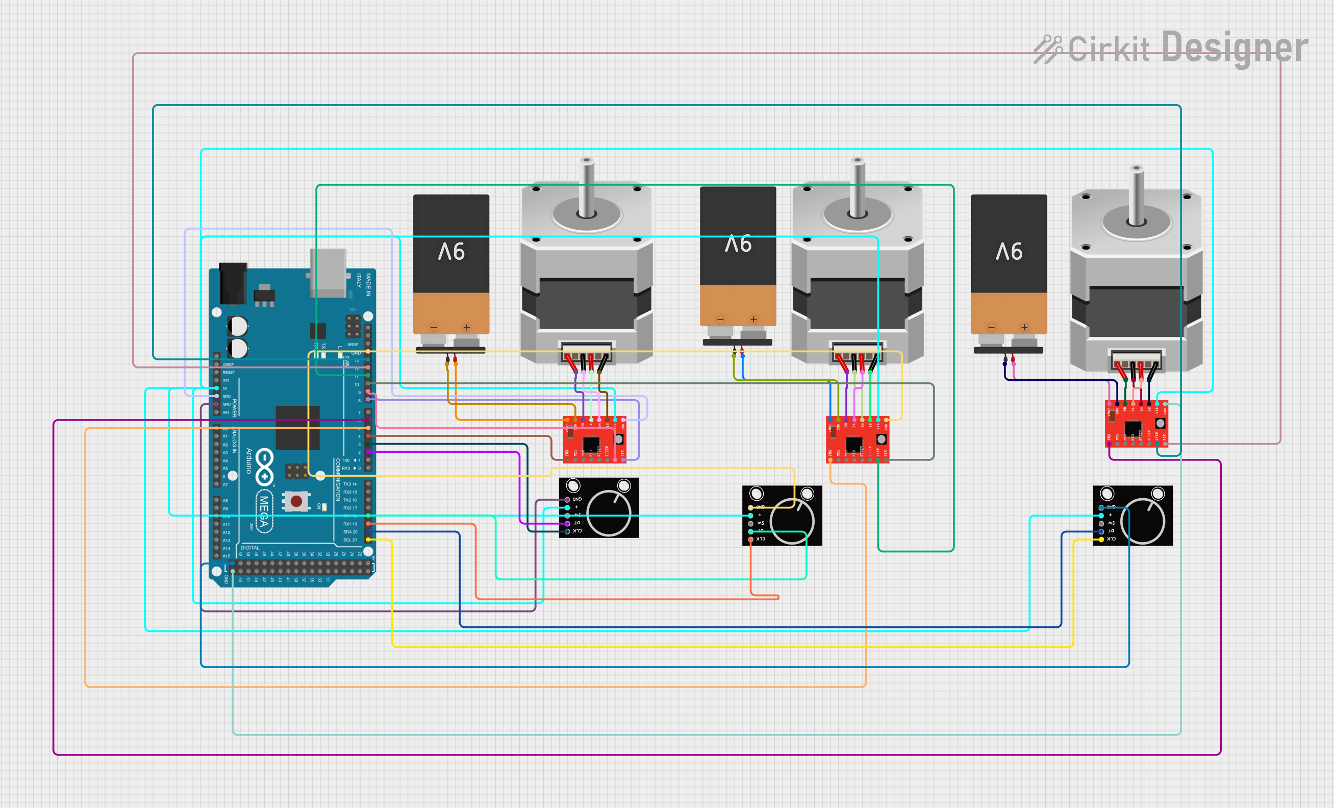


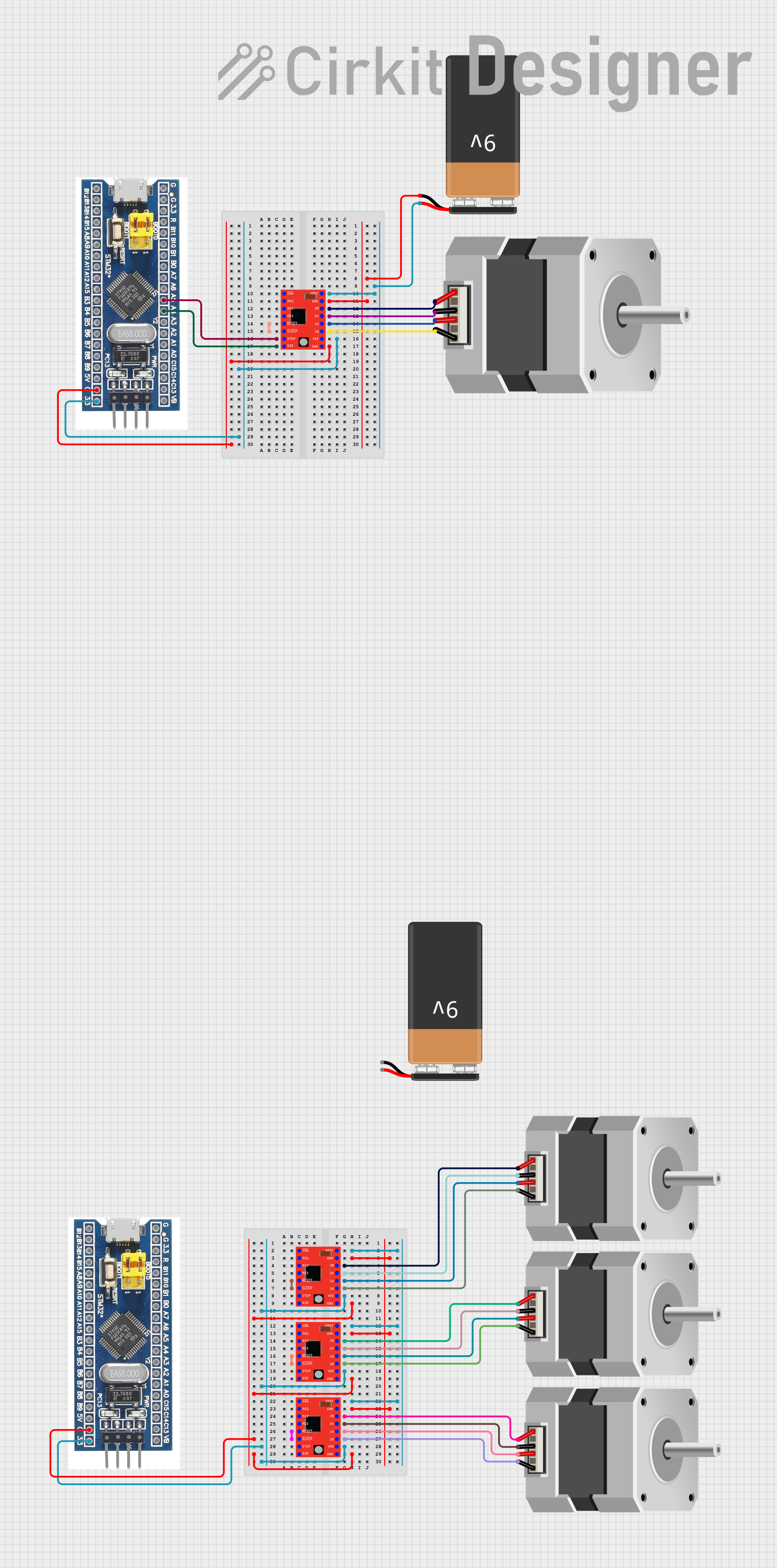
Explore Projects Built with A4983
Common Applications and Use Cases
- CNC machines
- 3D printers
- Robotics
- Precision positioning systems
- Automated equipment
Technical Specifications
Key Technical Details
- Logic Supply Voltage (VDD): 3.3 - 5.5 V
- Motor Supply Voltage (VMOT): 8 - 35 V
- Output Current: Up to 2 A per coil (with proper heat sinking)
- Micro-stepping: Full, 1/2, 1/4, and 1/16 steps
- Thermal Overload Protection: Yes
- Under-voltage Lockout: Yes
- Crossover-Current Protection: Yes
Pin Configuration and Descriptions
| Pin Number | Name | Description |
|---|---|---|
| 1 | VMOT | Motor supply voltage (8 - 35 V) |
| 2 | GND | Ground connection |
| 3 | 2B | Motor coil B connection |
| 4 | 2A | Motor coil A connection |
| 5 | 1A | Motor coil A connection |
| 6 | 1B | Motor coil B connection |
| 7 | VDD | Logic supply voltage (3.3 - 5.5 V) |
| 8 | GND | Ground connection |
| ... | ... | ... |
| n | STEP | Step input (pulses to control steps) |
| n+1 | DIR | Direction input (logic level to set direction) |
| n+2 | MS1 | Micro-stepping select 1 |
| n+3 | MS2 | Micro-stepping select 2 |
| n+4 | MS3 | Micro-stepping select 3 |
| n+5 | ENABLE | Enable motor output (active low) |
Note: The full pinout would continue based on the actual pin count of the A4983.
Usage Instructions
How to Use the Component in a Circuit
- Power Connections: Connect VMOT to the motor power supply and VDD to the logic power supply. Ensure that both grounds are connected to a common ground.
- Motor Connections: Connect the motor coils to the 1A, 1B, 2A, and 2B pins.
- Control Inputs: Connect the STEP and DIR pins to the controlling microcontroller or logic device.
- Micro-stepping Configuration: Set the MS1, MS2, and MS3 pins to logic high or low according to the desired micro-stepping resolution.
Important Considerations and Best Practices
- Use a decoupling capacitor close to the VMOT and VDD pins to minimize voltage spikes.
- Ensure that the current limit is set correctly to prevent damage to the motor or driver.
- Provide adequate heat sinking for the driver if operating at high currents.
- Avoid disconnecting the motor while the driver is powered to prevent damage.
Troubleshooting and FAQs
Common Issues Users Might Face
- Motor not moving: Check power supply voltages, wiring connections, and that the ENABLE pin is set to active low.
- Overheating: Ensure proper current limiting and heat sinking.
- Inconsistent stepping: Verify micro-stepping settings and that the STEP input is receiving clean pulses.
Solutions and Tips for Troubleshooting
- Double-check all connections and ensure that solder joints are solid and free of shorts.
- Use an oscilloscope to verify that the STEP and DIR signals are being received correctly by the A4983.
- If the motor vibrates but does not turn, try reducing the stepping speed or increasing the current limit.
Example Code for Arduino UNO
// Include the Arduino Stepper library
#include <Stepper.h>

// Define the number of steps per revolution
const int stepsPerRevolution = 200;

// Initialize the stepper library on pins 8 through 11
Stepper myStepper(stepsPerRevolution, 8, 9, 10, 11);

void setup() {
  // Set the speed at 60 rpm
  myStepper.setSpeed(60);
  // Begin Serial communication at a baud rate of 9600
  Serial.begin(9600);
}

void loop() {
  // Step one revolution in one direction
  Serial.println("clockwise");
  myStepper.step(stepsPerRevolution);
  delay(500);

  // Step one revolution in the other direction
  Serial.println("counterclockwise");
  myStepper.step(-stepsPerRevolution);
  delay(500);
}
Note: This example assumes the use of an Arduino library that abstracts away the direct handling of the A4983's STEP and DIR pins. For direct control, additional code would be required to manage these pins and the micro-stepping configuration.
Remember to adjust the stepsPerRevolution to match the specific stepper motor being used and the micro-stepping resolution configured on the A4983 driver.