How to Use power jack: Examples, Pinouts, and Specs

 Design with power jack in Cirkit Designer
Introduction
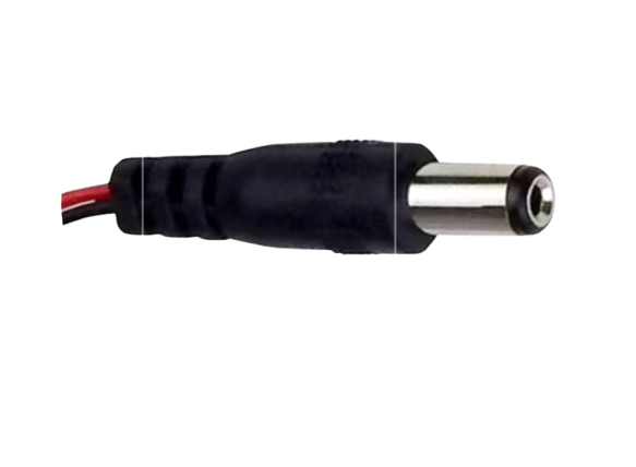
A power jack, also known as a DC power connector, is a type of electrical connector used to supply power to electronic devices from an external power source. It is a common component in various electronic devices such as laptops, routers, musical pedals, and other portable appliances. Power jacks are designed to accept power plugs of corresponding sizes and specifications, ensuring a secure and reliable electrical connection.
Explore Projects Built with power jack

 Open Project in Cirkit Designer
 Open Project in Cirkit Designer
 Open Project in Cirkit Designer
 Open Project in Cirkit Designer
Explore Projects Built with power jack

 Open Project in Cirkit Designer
 Open Project in Cirkit Designer
 Open Project in Cirkit Designer
 Open Project in Cirkit Designer
Common Applications and Use Cases
- Charging and powering laptops and notebooks
- Supplying power to desktop peripherals like routers and modems
- Providing power to small home appliances
- Powering electronic hobbyist projects, including Arduino-based circuits
- Use in musical equipment such as guitar pedals and synthesizers
Technical Specifications
Key Technical Details
- Rated Voltage: The maximum voltage the power jack can handle, typically ranging from 5V to 24V.
- Rated Current: The maximum current the power jack can carry, often between 1A to 5A.
- Contact Resistance: The electrical resistance between the plug and the jack, usually below 0.03 Ohms.
- Insulation Resistance: The electrical resistance between the conducting parts and the outer casing, typically above 100M Ohms.
- Durability: The number of insertion and removal cycles the jack can withstand without performance degradation, often rated at 5,000 to 10,000 cycles.
Pin Configuration and Descriptions
| Pin Number | Description | Notes |
|---|---|---|
| 1 | Ground Connection | Connected to the system ground |
| 2 | Power Connection | Positive voltage input |
| 3 (if present) | Switch Connection | Closes circuit when plug is removed |
Note: The pin configuration may vary depending on the specific model of the power jack. Always refer to the manufacturer's datasheet for exact details.
Usage Instructions
How to Use the Power Jack in a Circuit
- Identify the Polarity: Determine the polarity of the power supply and the power jack. The center pin is typically the positive terminal, while the outer sleeve is the negative terminal (ground).
- Select the Correct Power Supply: Ensure the power supply matches the rated voltage and current of the power jack.
- Soldering: Solder the power jack pins to the corresponding points on the PCB, ensuring a solid electrical connection without short circuits.
- Testing: Before applying power, use a multimeter to check for continuity and correct polarity.
- Connect the Power Supply: Insert the power plug into the jack gently to avoid damaging the connector.
Important Considerations and Best Practices
- Avoid exceeding the rated voltage and current to prevent damage to the power jack and the device.
- Use a strain relief on the power cable to prevent stress on the solder joints.
- Ensure proper insulation between the power jack terminals and the device chassis if it is conductive.
- Regularly inspect the power jack for signs of wear or damage, and replace if necessary.
Troubleshooting and FAQs
Common Issues Users Might Face
- Loose Connections: If the device intermittently loses power, check for loose solder joints or a worn-out power jack.
- No Power: Ensure the power supply is functioning and the polarity matches. Check for any broken connections.
- Overheating: If the power jack overheats, it may indicate an overcurrent situation. Verify that the current draw is within the rated specifications.
Solutions and Tips for Troubleshooting
- Resoldering: If the connection is loose, resolder the power jack to the PCB.
- Replacement: Replace the power jack if it is physically damaged or worn out.
- Polarity Check: Use a multimeter to confirm the polarity of the power supply and the power jack if there is no power.
FAQs
Q: Can I use any power supply with my power jack? A: No, the power supply must match the rated voltage and current of the power jack.
Q: How do I know if my power jack is damaged? A: Common signs include loose connections, difficulty inserting the plug, or visible wear and damage.
Q: Is it safe to solder the power jack while the power is connected? A: No, always disconnect the power before soldering to avoid the risk of electric shock or damage to the device.
Q: Can I use a power jack with a higher rating than my device requires? A: Yes, using a power jack with a higher rating is generally safe, but the power supply must still match the device's requirements.
Note: This documentation is for informational purposes only. Always consult the manufacturer's datasheet and follow safety guidelines when working with electronic components.