How to Use IF HW 870: Examples, Pinouts, and Specs
Introduction
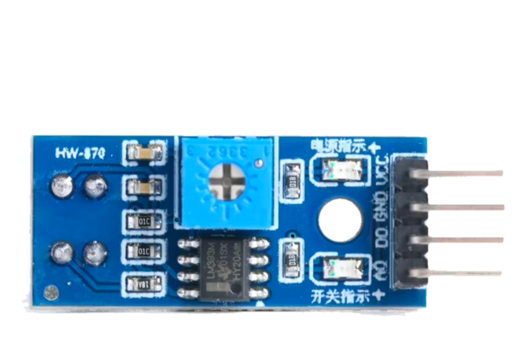
The IF HW 870 is an intermediate frequency (IF) filter designed for radio frequency (RF) applications. It is used to select specific frequency bands while rejecting unwanted frequencies, ensuring signal clarity and reducing interference. This component is essential in communication systems, radio receivers, and other RF circuits where precise frequency filtering is required.
Explore Projects Built with IF HW 870


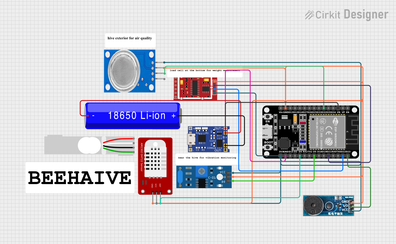
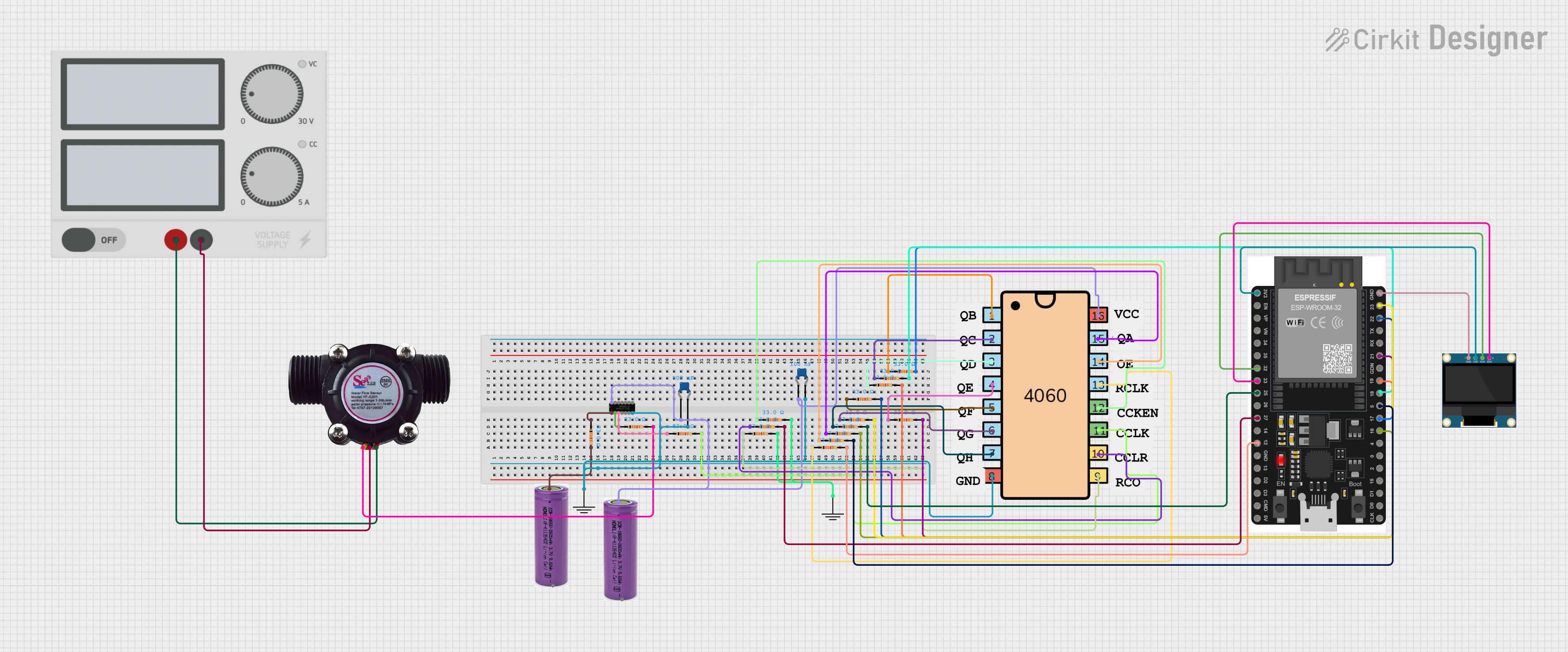
Explore Projects Built with IF HW 870
Common Applications
- Radio receivers for AM/FM/SSB signals
- Communication systems (e.g., transceivers)
- Spectrum analyzers and signal processing equipment
- RF front-end circuits for noise reduction and signal clarity
Technical Specifications
Key Technical Details
| Parameter | Value |
|---|---|
| Center Frequency (Fc) | 10.7 MHz |
| Bandwidth | ±15 kHz |
| Insertion Loss | ≤ 3 dB |
| Stopband Attenuation | ≥ 40 dB |
| Impedance | 330 Ω |
| Operating Temperature | -20°C to +70°C |
| Package Type | DIP (Dual Inline Package) |
Pin Configuration and Descriptions
| Pin Number | Name | Description |
|---|---|---|
| 1 | Input | Signal input pin for the IF filter |
| 2 | Ground (GND) | Ground connection for the filter |
| 3 | Output | Filtered signal output pin |
| 4 | Ground (GND) | Additional ground connection for stability |
Usage Instructions
How to Use the IF HW 870 in a Circuit
- Power and Ground Connections: Connect the ground pins (Pin 2 and Pin 4) to the circuit's ground plane to ensure proper operation and minimize noise.
- Signal Input: Feed the intermediate frequency signal into the input pin (Pin 1). Ensure the signal is within the filter's operating range (centered around 10.7 MHz).
- Filtered Output: The filtered signal will be available at the output pin (Pin 3). Connect this pin to the next stage of your circuit, such as an amplifier or demodulator.
- Impedance Matching: Ensure the input and output impedances match the filter's rated impedance (330 Ω) to minimize signal loss and reflections.
Important Considerations and Best Practices
- Bypass Capacitors: Place bypass capacitors (e.g., 0.1 µF) near the ground pins to reduce high-frequency noise.
- PCB Layout: Use a clean and well-grounded PCB layout to avoid introducing noise or interference into the filter.
- Signal Levels: Avoid exceeding the maximum input signal level to prevent distortion or damage to the filter.
- Temperature Range: Operate the filter within its specified temperature range (-20°C to +70°C) to ensure reliable performance.
Example: Connecting the IF HW 870 to an Arduino UNO
While the IF HW 870 is not directly programmable, it can be used in conjunction with an Arduino UNO for signal processing. Below is an example of how to measure the filtered signal using the Arduino's analog input.
// Example: Reading the filtered signal from the IF HW 870 using Arduino UNO
// Connect the output of the IF HW 870 to Arduino's analog pin A0

const int analogPin = A0;  // Define the analog pin connected to the filter output
int signalValue = 0;       // Variable to store the analog signal value

void setup() {
  Serial.begin(9600);  // Initialize serial communication at 9600 baud
}

void loop() {
  signalValue = analogRead(analogPin);  // Read the analog signal value
  Serial.print("Filtered Signal Value: ");
  Serial.println(signalValue);  // Print the signal value to the Serial Monitor
  delay(100);  // Delay for 100 ms before the next reading
}
Note: The Arduino UNO's ADC (Analog-to-Digital Converter) can only measure voltage levels. Ensure the filtered signal is within the Arduino's input voltage range (0-5V) by using a voltage divider or amplifier if necessary.
Troubleshooting and FAQs
Common Issues and Solutions
| Issue | Possible Cause | Solution |
|---|---|---|
| No output signal | Incorrect wiring or loose connections | Verify all connections and ensure proper wiring. |
| High insertion loss | Impedance mismatch | Match the input/output impedance to 330 Ω. |
| Excessive noise in the output | Poor grounding or PCB layout issues | Improve grounding and minimize trace lengths. |
| Signal distortion | Input signal exceeds filter limits | Ensure the input signal is within the filter's range. |
FAQs
Q: Can the IF HW 870 be used for frequencies other than 10.7 MHz?
A: No, the IF HW 870 is specifically designed for a center frequency of 10.7 MHz. Using it for other frequencies will result in poor performance.
Q: How do I test if the filter is working correctly?
A: Use a signal generator to input a 10.7 MHz signal and measure the output with an oscilloscope. The output should show the filtered signal with reduced noise.
Q: Can I use the IF HW 870 in high-power RF circuits?
A: The IF HW 870 is designed for low-power applications. For high-power circuits, consider using a filter with higher power handling capabilities.
Q: What happens if I operate the filter outside its temperature range?
A: Operating the filter outside its specified temperature range (-20°C to +70°C) may result in degraded performance or permanent damage. Always ensure the operating environment is within the specified range.