
How to Use Fan: Examples, Pinouts, and Specs
 Design with Fan in Cirkit Designer
Introduction
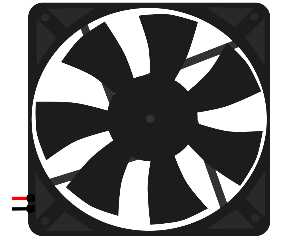
A fan is an electromechanical device that creates airflow to cool or ventilate an area. It is commonly used in electronic enclosures, such as computer cases, power supplies, and other devices, to dissipate heat and maintain optimal operating temperatures. Fans are essential for preventing overheating, ensuring the longevity of components, and maintaining system performance.
Explore Projects Built with Fan
 Open Project in Cirkit Designer
 Open Project in Cirkit Designer
 Open Project in Cirkit Designer
 Open Project in Cirkit Designer
Explore Projects Built with Fan
Open Project in Cirkit DesignerOpen Project in Cirkit DesignerOpen Project in Cirkit DesignerOpen Project in Cirkit DesignerCommon Applications and Use Cases
- Cooling electronic components in computers, power supplies, and servers.
- Ventilating enclosures for industrial equipment.
- Enhancing airflow in HVAC systems.
- Used in DIY electronics projects for temperature regulation.
- Cooling 3D printers, robotics, and other embedded systems.
Technical Specifications
Below are the general technical specifications for a standard DC brushless fan commonly used in electronics:
| Parameter | Value |
|---|---|
| Operating Voltage | 5V, 12V, or 24V (depending on model) |
| Current Consumption | 0.1A to 0.5A |
| Power Rating | 0.5W to 5W |
| Speed | 1000 to 5000 RPM |
| Airflow | 10 to 100 CFM (Cubic Feet per Minute) |
| Noise Level | 20 to 40 dBA |
| Bearing Type | Sleeve or Ball Bearing |
| Connector Type | 2-pin, 3-pin, or 4-pin |
| Dimensions | 40mm x 40mm, 80mm x 80mm, 120mm x 120mm (common sizes) |
Pin Configuration and Descriptions
The pin configuration for a 3-pin and 4-pin fan is detailed below:
3-Pin Fan
| Pin | Name | Description |
|---|---|---|
| 1 | GND | Ground connection for the fan. |
| 2 | VCC | Positive voltage supply (e.g., 12V). |
| 3 | Tachometer | Outputs a signal for fan speed monitoring (optional). |
4-Pin Fan
| Pin | Name | Description |
|---|---|---|
| 1 | GND | Ground connection for the fan. |
| 2 | VCC | Positive voltage supply (e.g., 12V). |
| 3 | Tachometer | Outputs a signal for fan speed monitoring. |
| 4 | PWM | Pulse Width Modulation input for speed control. |
Usage Instructions
How to Use the Fan in a Circuit
- Power Supply: Ensure the fan is powered with the correct voltage (e.g., 5V, 12V, or 24V) as specified in its datasheet. Exceeding the rated voltage can damage the fan.
- Connections:
- For a 2-pin fan, connect the VCC pin to the positive terminal of the power supply and the GND pin to the ground.
- For a 3-pin fan, connect the VCC and GND pins as above, and optionally connect the Tachometer pin to a microcontroller or monitoring circuit to measure fan speed.
- For a 4-pin fan, connect the PWM pin to a microcontroller or PWM signal generator for speed control.
- Mounting: Secure the fan in place using screws or clips to ensure proper airflow direction. Most fans have an arrow indicating the airflow direction.
Important Considerations and Best Practices
- Airflow Direction: Ensure the fan is oriented correctly to direct airflow where needed. The fan casing typically has arrows indicating the airflow and blade rotation direction.
- Noise Reduction: Use rubber mounts or grommets to reduce vibration and noise.
- PWM Control: For 4-pin fans, use a PWM signal (typically 25 kHz) to adjust the fan speed dynamically.
- Dust Management: Regularly clean the fan and surrounding area to prevent dust buildup, which can reduce efficiency and increase noise.
- Current Rating: Ensure the power supply can provide sufficient current for the fan's operation.
Example: Controlling a 4-Pin Fan with Arduino UNO
Below is an example of how to control a 4-pin fan using an Arduino UNO and PWM:
// Define the PWM pin connected to the fan's PWM input
const int fanPWMPin = 9;

void setup() {
  // Set the PWM pin as an output
  pinMode(fanPWMPin, OUTPUT);
}

void loop() {
  // Set fan speed to 50% (128 out of 255)
  analogWrite(fanPWMPin, 128);
  delay(5000); // Run at 50% speed for 5 seconds

  // Set fan speed to 100% (255 out of 255)
  analogWrite(fanPWMPin, 255);
  delay(5000); // Run at full speed for 5 seconds

  // Set fan speed to 0% (0 out of 255) - fan off
  analogWrite(fanPWMPin, 0);
  delay(5000); // Fan off for 5 seconds
}
Troubleshooting and FAQs
Common Issues and Solutions
Fan Not Spinning:
- Cause: Incorrect voltage or loose connections.
- Solution: Verify the power supply voltage matches the fan's rated voltage. Check all connections.
Fan is Noisy:
- Cause: Dust buildup, worn bearings, or improper mounting.
- Solution: Clean the fan blades and surrounding area. Replace the fan if the bearings are worn. Use rubber mounts to reduce vibration.
Fan Speed Not Adjustable:
- Cause: PWM signal not configured correctly or using a non-PWM fan.
- Solution: Ensure the fan supports PWM control (4-pin). Verify the PWM signal frequency and duty cycle.
Fan Overheats or Fails Prematurely:
- Cause: Operating at incorrect voltage or in a high-temperature environment.
- Solution: Use the fan within its rated voltage and temperature range. Ensure proper ventilation.
FAQs
Q: Can I use a 3-pin fan with a 4-pin connector?
A: Yes, but you will not have PWM speed control. The fan will run at full speed.Q: How do I determine the airflow direction?
A: Look for the arrows on the fan casing indicating airflow and blade rotation direction.Q: Can I connect a fan directly to an Arduino?
A: No, most fans require more current than an Arduino pin can supply. Use a transistor or MOSFET to drive the fan.Q: What is the purpose of the Tachometer pin?
A: It provides a signal to measure the fan's speed (RPM), which can be monitored by a microcontroller.
By following this documentation, you can effectively integrate and troubleshoot a fan in your electronic projects.