How to Use Hex Inverter: Examples, Pinouts, and Specs
Introduction
The Hex Inverter is a digital logic component that inverts the input signal, providing six independent inverter gates in a single package. Each gate takes a single input and produces an output that is the logical NOT of the input. This component is widely used in digital circuits for signal inversion, waveform shaping, and logic-level manipulation.
Explore Projects Built with Hex Inverter

Explore Projects Built with Hex Inverter
Common Applications and Use Cases
- Signal inversion in digital circuits
- Waveform generation and shaping
- Logic-level conversion
- Clock signal manipulation
- Used in microcontroller-based projects for signal conditioning
Technical Specifications
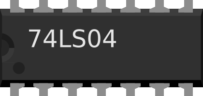
Below are the key technical details for a standard Hex Inverter, such as the 74HC04 or 74LS04:
| Parameter | Value |
|---|---|
| Supply Voltage (Vcc) | 2V to 6V (74HC04), 4.75V to 5.25V (74LS04) |
| Input Voltage Range | 0V to Vcc |
| Output Voltage Range | 0V to Vcc |
| High-Level Output Current | -20 mA |
| Low-Level Output Current | 20 mA |
| Propagation Delay | ~10 ns (74HC04), ~22 ns (74LS04) |
| Power Dissipation | ~500 mW |
| Operating Temperature | -40°C to +85°C |
Pin Configuration and Descriptions
The Hex Inverter is typically available in a 14-pin Dual In-line Package (DIP). Below is the pinout and description:
| Pin Number | Pin Name | Description |
|---|---|---|
| 1 | A1 | Input to inverter gate 1 |
| 2 | Y1 | Output of inverter gate 1 |
| 3 | A2 | Input to inverter gate 2 |
| 4 | Y2 | Output of inverter gate 2 |
| 5 | A3 | Input to inverter gate 3 |
| 6 | Y3 | Output of inverter gate 3 |
| 7 | GND | Ground (0V) |
| 8 | Y4 | Output of inverter gate 4 |
| 9 | A4 | Input to inverter gate 4 |
| 10 | Y5 | Output of inverter gate 5 |
| 11 | A5 | Input to inverter gate 5 |
| 12 | Y6 | Output of inverter gate 6 |
| 13 | A6 | Input to inverter gate 6 |
| 14 | Vcc | Positive supply voltage |
Usage Instructions
How to Use the Hex Inverter in a Circuit
- Power the Component: Connect the Vcc pin to a suitable power supply (e.g., 5V for 74LS04) and the GND pin to ground.
- Connect Inputs and Outputs: For each inverter gate, connect the input signal to the corresponding
Apin (e.g., A1, A2) and take the inverted output from the correspondingYpin (e.g., Y1, Y2). - Load Considerations: Ensure the output load does not exceed the maximum current rating (20 mA) to avoid damage.
- Bypass Capacitor: Place a 0.1 µF ceramic capacitor between Vcc and GND to filter noise and stabilize the power supply.
Example Circuit
Below is an example of using a Hex Inverter to invert a digital signal:
- Input Signal: A square wave from a microcontroller (e.g., Arduino UNO).
- Output Signal: The inverted square wave.
// Example Arduino code to demonstrate Hex Inverter usage
// This code generates a square wave on pin 8, which can be inverted
// using a Hex Inverter connected to the Arduino.

void setup() {
  pinMode(8, OUTPUT); // Set pin 8 as an output
}

void loop() {
  digitalWrite(8, HIGH); // Set pin 8 HIGH
  delay(500);            // Wait for 500 ms
  digitalWrite(8, LOW);  // Set pin 8 LOW
  delay(500);            // Wait for 500 ms
}
Important Considerations and Best Practices
- Unused Inputs: Always connect unused inputs to GND or Vcc to prevent floating inputs, which can cause erratic behavior.
- Voltage Levels: Ensure the input voltage levels are within the specified range for the Hex Inverter model you are using.
- Propagation Delay: Consider the propagation delay when designing high-speed circuits.
Troubleshooting and FAQs
Common Issues and Solutions
No Output Signal:
- Cause: Power supply not connected or incorrect voltage.
- Solution: Verify the Vcc and GND connections and ensure the supply voltage is within the specified range.
Erratic Behavior:
- Cause: Floating inputs or noisy power supply.
- Solution: Connect all unused inputs to GND or Vcc and add a bypass capacitor between Vcc and GND.
Output Signal Distortion:
- Cause: Exceeding the maximum output current rating.
- Solution: Reduce the load on the output or use a buffer circuit.
Component Overheating:
- Cause: Excessive power dissipation.
- Solution: Check the circuit design and ensure the power dissipation is within the specified limits.
FAQs
Q1: Can I use the Hex Inverter with a 3.3V system?
A1: Yes, models like the 74HC04 can operate with supply voltages as low as 2V, making them compatible with 3.3V systems.
Q2: What happens if I leave an input pin unconnected?
A2: Floating inputs can cause unpredictable behavior. Always connect unused inputs to GND or Vcc.
Q3: Can I cascade multiple inverter gates?
A3: Yes, you can connect the output of one inverter to the input of another to achieve specific logic functions or signal conditioning.
Q4: Is the Hex Inverter suitable for analog signals?
A4: No, the Hex Inverter is designed for digital signals. Using it with analog signals may result in undefined behavior.